Alignment & Troubleshooting
Service Manual
4-90
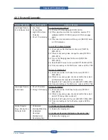
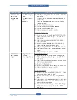
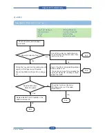
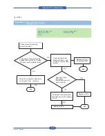
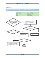
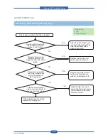
Problem Description
Cause Description
Action to Resolve
Color OPC BLDC
Motor Error
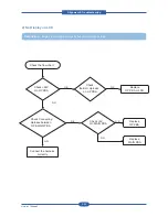
1. High Torque Loaded
on OPC Unit
[1. High Torque Loaded on OPC Unit]
1.1) Check the torque OPC Unit
1.2) If the torque is very high. replace OPC Unit
[2. Motor Signal is abnormal]
1.1) Check the wire connection from motor to Engine PBA.
1.2) If the connection is wrong , correct it .
1.3) If the connection is right , replace motor and/or harness .
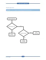
Fuser BLDC Motor
Error
1. High Torque Loaded
on Fuser Unit
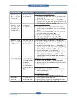
[1. High Torque Loaded on Fuser Unit]
1.1) Check the torque Fuser Unit
1.2) If the torque is very high. replace Fuser Unit
[2. Motor Signal is abnormal]
1.1) Check the wire connection from motor to Engine PBA.
1.2) If the connection is wrong , correct it .
1.3) If the connection is right , replace motor and/or harness .
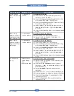
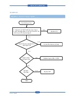
Fuser Open Error
1. Thermistor Open
2. Thermostat Open
3. T2 Transfer Mis-
Contact
4. Engine PBA Error
[1. Thermistor Open]
1.1) Check resistance of thermistors.
1.2) If the resistance value is infinite or much high (Mohm),
replace the thermistor or Fuser Unit.
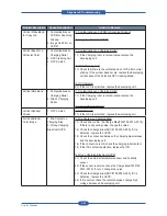
[2. Thermostat Open]
2.1) Check resistance of thermostats.
2.2) If the resistance value is infinite or much high (Mohm),
replace the thermostat or Fuser Unit.
[3. T2 Transfer Mis-Contact]
3.1) Open the side cover and check high voltage contacts of T2
roller.
3.2) If there are any contaminations on the contact, make it
clean.
[4. Engine PBA Error]
4.1) If there is no problems in the above 3 checks, and the error
is continuously displayed, replace Engine PBA.
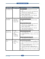
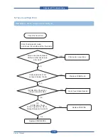
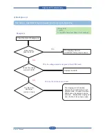
No Booting
1. Power Out
2. Fail to Initialize
Video PBA
[1. Power Out]
1.1) Check and confirm 5V output from SMPS.
1.2) Check power wire connections from SMPS to Engine PBA.
1.3) Check core voltages in Video/Engine PBA.
[2. Fail to Initialize Video PBA]
2.1) Check the connections of DIMM Memory, HDD, and GUI
interface harness.
2.2) Reboot the set.
2.3) If the set does not initialize, replace the Video PBA.
Summary of Contents for MFX-C4000
Page 2: ......
Page 14: ...Precautions Service Manual 1 6 ...
Page 35: ...Service Manual 2 21 Video Controller Power Distribution Product Specifications and Features ...
Page 37: ...Service Manual 2 23 Engine Controller Power Distribution Product Specifications and Features ...
Page 39: ...Service Manual 2 25 DADF Block Diagram Product Specifications and Features ...
Page 106: ...Maintenance and Disassembly Service Manual 3 44 ...
Page 216: ...Alignment Troubleshooting Service Manual 4 110 ...
Page 217: ...System Diagram Service Manual 5 1 5 System Diagram 5 1 Block Diagram 5 1 1 System ...
Page 218: ...System Diagram Service Manual 5 2 5 1 2 Video Controller ...
Page 219: ...System Diagram Service Manual 5 3 5 1 3 Engin Controller ...
Page 220: ...System Diagram Service Manual 5 4 5 1 4 OPE Unit ...
Page 221: ...System Diagram Service Manual 5 5 5 1 5 DADF ...
Page 222: ...System Diagram Service Manual 5 6 5 1 6 SCF HCF ...
Page 225: ...System Diagram Service Manual 5 9 5 2 3 OPE Unit ...
Page 226: ...System Diagram Service Manual 5 10 5 2 4 DADF ...
Page 227: ...System Diagram Service Manual 5 11 5 2 5 SCF HCF ...
Page 228: ...System Diagram Service Manual 5 12 ...
Page 237: ...Reference Information Service Manual 6 9 ...
Page 238: ...Reference Information Service Manual 6 10 ...
Page 239: ...Reference Information Service Manual 6 11 ...
Page 240: ...Reference Information Service Manual 6 12 ...
Page 279: ......

