Alignment & Troubleshooting
Service Manual
4-78
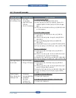
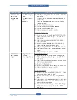
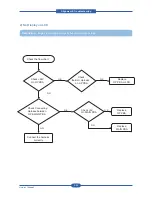
4.2.3 System Diagnostic
Problem Description
Cause Description
Action to Resolve
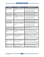
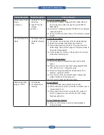
Low Image Density
for a Particular Color
1. Low Toner
Concentration
2. High OPC Surface
Potential
3. Poor T1 Transferring
[1. Low Toner Concentration]
1.1) Print out CTD check page [EDC #117-0001].
1.2) If the output has low toner concentration, execute CTD
calibration [EDC #117-0000], and print CTD check page
again.
1.3) If the toner concentration is still low, go to [DE-003] Failure
in CTD Calibration.
[2. High OPC Surface Potential]
2.1) Check and confirm MHV Bias for the color [TM #105-
0000~0016].
2.2) If there is any wrong value, change the value [TM #105-
0000~0016].
2.3) Turn on the Charging Bias for the color [EDC #105-
0000~0003]
2.4) Read the MHV value for the color [EDC #105-0004~0007]
2.5) If any mis-reading on the MHV value, replace HVPS-L PBA.
[3. Poor T1 Transferring]
3.1) Check and confirm THV1 Bias for the color [TM #107-
0000~0007]
3.2) If there is any wrong value, check and confirm the contact
point between the rear side of ITB and frame.
3.3) Read the THV1 value for the color [EDC #107-0000~0003]
3.4) If any mis-reading on the MHV value, replace HVPS-L PBA.
Low Image Density
for All Colors
1. Poor T2 Transfer
2. Wrong CTD Sensing
[1. Poor T2 Transfer]
1.1) Check and confirm THV2 Bias for the color [TM #107-
0008~0009]
1.2) If there is any wrong value, check and confirm the contact
point of T2 driving roller in side unit.
1.3) Read the THV2 value for the color [EDC #107-0004~0007]
1.4) If any mis-reading on the THV2 value, replace HVPS-L
PBA.
Vertical Irregular
Image Density for a
Particular Color
1. Unbalanced
Metering Blade Gap
2. Unbalanced
Developer
Distribution at
Developing Gap
[1. Unbalanced Metering Blade Gap]
1.1) Replace the Imaging unit.
[2. Unbalanced Developer Distribution at Developing Gap]
2.1) Replace the Imaging unit.
Summary of Contents for MFX-C4000
Page 2: ......
Page 14: ...Precautions Service Manual 1 6 ...
Page 35: ...Service Manual 2 21 Video Controller Power Distribution Product Specifications and Features ...
Page 37: ...Service Manual 2 23 Engine Controller Power Distribution Product Specifications and Features ...
Page 39: ...Service Manual 2 25 DADF Block Diagram Product Specifications and Features ...
Page 106: ...Maintenance and Disassembly Service Manual 3 44 ...
Page 216: ...Alignment Troubleshooting Service Manual 4 110 ...
Page 217: ...System Diagram Service Manual 5 1 5 System Diagram 5 1 Block Diagram 5 1 1 System ...
Page 218: ...System Diagram Service Manual 5 2 5 1 2 Video Controller ...
Page 219: ...System Diagram Service Manual 5 3 5 1 3 Engin Controller ...
Page 220: ...System Diagram Service Manual 5 4 5 1 4 OPE Unit ...
Page 221: ...System Diagram Service Manual 5 5 5 1 5 DADF ...
Page 222: ...System Diagram Service Manual 5 6 5 1 6 SCF HCF ...
Page 225: ...System Diagram Service Manual 5 9 5 2 3 OPE Unit ...
Page 226: ...System Diagram Service Manual 5 10 5 2 4 DADF ...
Page 227: ...System Diagram Service Manual 5 11 5 2 5 SCF HCF ...
Page 228: ...System Diagram Service Manual 5 12 ...
Page 237: ...Reference Information Service Manual 6 9 ...
Page 238: ...Reference Information Service Manual 6 10 ...
Page 239: ...Reference Information Service Manual 6 11 ...
Page 240: ...Reference Information Service Manual 6 12 ...
Page 279: ......


