Alignment & Troubleshooting
Service Manual
4-46
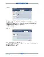
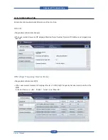
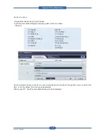
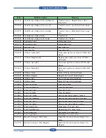
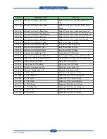
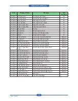
Fault Counters Detail window shall display Fault code, description and value (counter) among the selected
Fault Group. Items of displayed Fault codes are different based on the selection of ‘Non Zero’ or ‘All’. When
selected ‘Non Zero’, Fault codes in the selected Fault Group having non zero counter shall be displayed.
When selected ‘All’, all Fault codes in the selected Fault Group shall be displayed. Display order of Fault
code is upward.
4.1.8.7 Test Routines Tab
4.1.8.7(a) Copier
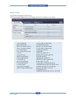
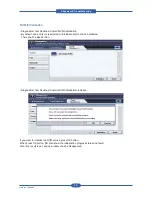
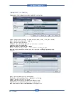
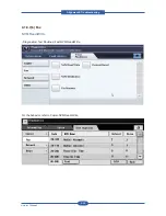
NVM Read/Write
• Diagnostics>Test Routines>Copier>NVM Read/Write
“Edit” button shall be disabled until any NVM item is selected.
“Edit” button shall be disabled when read only NVM is selected. Search edit box has 00-000 as a default.
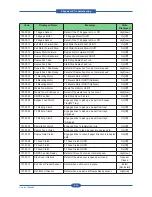
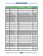
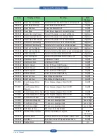
User shall input the whole number to find a specific NVM by pressing Find button. (Refer to NVM Read/Write
table) If matching NVM is found, the page including the specified NVM shall be displayed and the NVM is
shown as selected. If matching NVM is not found, error message such as “Invalid NVM number” shall be
displayed on the status area and search edit box displays default number.
Summary of Contents for MFX-C4000
Page 2: ......
Page 14: ...Precautions Service Manual 1 6 ...
Page 35: ...Service Manual 2 21 Video Controller Power Distribution Product Specifications and Features ...
Page 37: ...Service Manual 2 23 Engine Controller Power Distribution Product Specifications and Features ...
Page 39: ...Service Manual 2 25 DADF Block Diagram Product Specifications and Features ...
Page 106: ...Maintenance and Disassembly Service Manual 3 44 ...
Page 216: ...Alignment Troubleshooting Service Manual 4 110 ...
Page 217: ...System Diagram Service Manual 5 1 5 System Diagram 5 1 Block Diagram 5 1 1 System ...
Page 218: ...System Diagram Service Manual 5 2 5 1 2 Video Controller ...
Page 219: ...System Diagram Service Manual 5 3 5 1 3 Engin Controller ...
Page 220: ...System Diagram Service Manual 5 4 5 1 4 OPE Unit ...
Page 221: ...System Diagram Service Manual 5 5 5 1 5 DADF ...
Page 222: ...System Diagram Service Manual 5 6 5 1 6 SCF HCF ...
Page 225: ...System Diagram Service Manual 5 9 5 2 3 OPE Unit ...
Page 226: ...System Diagram Service Manual 5 10 5 2 4 DADF ...
Page 227: ...System Diagram Service Manual 5 11 5 2 5 SCF HCF ...
Page 228: ...System Diagram Service Manual 5 12 ...
Page 237: ...Reference Information Service Manual 6 9 ...
Page 238: ...Reference Information Service Manual 6 10 ...
Page 239: ...Reference Information Service Manual 6 11 ...
Page 240: ...Reference Information Service Manual 6 12 ...
Page 279: ......

