Service Manual
2-31
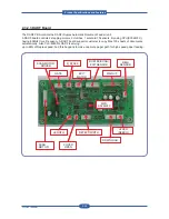
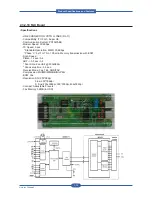
2.3.2.7 Fuser Drive Board
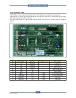
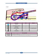
The FDB (Fuser Drive Board) controls 2 halogen lamps in the fuser unit using control signals which are
provided from the ENGINE PBA and supplies AC power to the SMPS. Both V1/V2 FDBs provide max.
1500W output power.
When the phase signal of AC Power goes to zero, the FDB sends a zero-crossing detect signal to the
ENGINE PBA. The zero-crossing output consists an open-collector node.
• Connection
1
INLET AC
2
FUSER CONTROL (from Main board)
3
FUSER AC (to Fuser lamp)
4
SMPS AC ( to SMPS)
• Specification
V1
V2
Input Voltage
(Range)
AC 110V
(90 ~ 135V)
AC 220V
(180 ~ 270V)
Input Current
20A
10A
Output Power
Max. 1500W
Max. 1500W
Phase Detect
Zero-Crossing Detect
(Open Collector Output)
Protection
Relay Control Signal
2
1
4
3
FUSE
VARISTOR
PHOTO TRAIC
HEAT SINK
2
1
4
3
Product
S
pec
ifications
and
F
eature
s
Summary of Contents for MFX-C4000
Page 2: ......
Page 14: ...Precautions Service Manual 1 6 ...
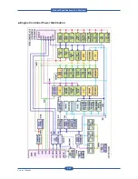
Page 35: ...Service Manual 2 21 Video Controller Power Distribution Product Specifications and Features ...
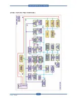
Page 37: ...Service Manual 2 23 Engine Controller Power Distribution Product Specifications and Features ...
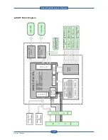
Page 39: ...Service Manual 2 25 DADF Block Diagram Product Specifications and Features ...
Page 106: ...Maintenance and Disassembly Service Manual 3 44 ...
Page 216: ...Alignment Troubleshooting Service Manual 4 110 ...
Page 217: ...System Diagram Service Manual 5 1 5 System Diagram 5 1 Block Diagram 5 1 1 System ...
Page 218: ...System Diagram Service Manual 5 2 5 1 2 Video Controller ...
Page 219: ...System Diagram Service Manual 5 3 5 1 3 Engin Controller ...
Page 220: ...System Diagram Service Manual 5 4 5 1 4 OPE Unit ...
Page 221: ...System Diagram Service Manual 5 5 5 1 5 DADF ...
Page 222: ...System Diagram Service Manual 5 6 5 1 6 SCF HCF ...
Page 225: ...System Diagram Service Manual 5 9 5 2 3 OPE Unit ...
Page 226: ...System Diagram Service Manual 5 10 5 2 4 DADF ...
Page 227: ...System Diagram Service Manual 5 11 5 2 5 SCF HCF ...
Page 228: ...System Diagram Service Manual 5 12 ...
Page 237: ...Reference Information Service Manual 6 9 ...
Page 238: ...Reference Information Service Manual 6 10 ...
Page 239: ...Reference Information Service Manual 6 11 ...
Page 240: ...Reference Information Service Manual 6 12 ...
Page 279: ......

