Alignment & Troubleshooting
Service Manual
4-20
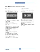
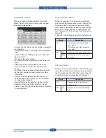
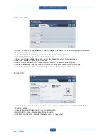
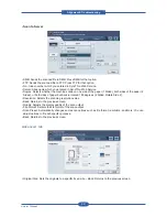
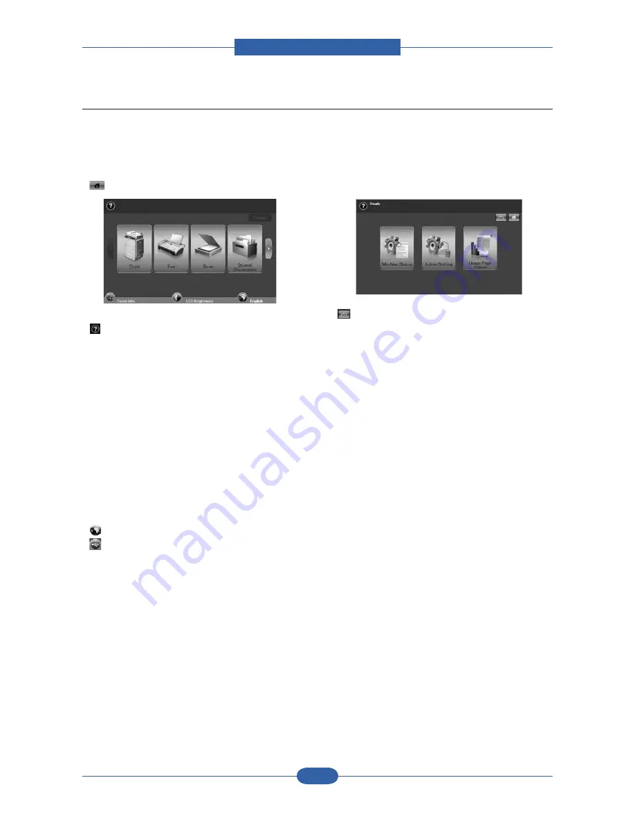
Touch screen
The touch screen allows for user-friendly operation
of the machine. Once you press the home icon
(
) on the screen, it shows the Main screen.
• : Shows Help. You can find the explanation by
feature contents.
• Copy: Enters the Copy menu.
• Fax: Enters the Fax menu. (Optional)
• Scan: Enters Scan to Email, NetScan, Scan to
Server menu.
• Stored Documents: Enters the Stored Documents
menu.
• USB: When USB memory is inserted into the USB
memory port on your machine, USB icon shows
on the display screen.
• SmarThru Workflow: Enters the SmarThru
Workflow menu.
(Optional)
• Toner Info.: Shows amount of toner used.
• LCD Brightness: Adjusts the brightness of the
touch screen.
• : You can change the display language.
• : Guides you to remove the USB memory
devices from the machine. Follow the instruction
on the LCD. This icon appears only when you
connect an USB memory module.
• Logout: Logs out from the currently logged in
account.
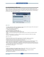
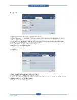
Machine Setup button
When you press Machine Setup button, you
can browse current machine settings or change
machine values.
•
This button allows you to move to Copy, Fax,
Scan, Stored Documents menu directly.
• Machine Status: Shows the current status of the
machine.
• Admin Setting: Allows an administrator to set up
the machine.
• Usage Page Report:You can print the report on
the amount of printouts depending on the paper
size and type.
4.1.4.1 Introducing the touch screen and useful buttons
Summary of Contents for MFX-C4000
Page 2: ......
Page 14: ...Precautions Service Manual 1 6 ...
Page 35: ...Service Manual 2 21 Video Controller Power Distribution Product Specifications and Features ...
Page 37: ...Service Manual 2 23 Engine Controller Power Distribution Product Specifications and Features ...
Page 39: ...Service Manual 2 25 DADF Block Diagram Product Specifications and Features ...
Page 106: ...Maintenance and Disassembly Service Manual 3 44 ...
Page 216: ...Alignment Troubleshooting Service Manual 4 110 ...
Page 217: ...System Diagram Service Manual 5 1 5 System Diagram 5 1 Block Diagram 5 1 1 System ...
Page 218: ...System Diagram Service Manual 5 2 5 1 2 Video Controller ...
Page 219: ...System Diagram Service Manual 5 3 5 1 3 Engin Controller ...
Page 220: ...System Diagram Service Manual 5 4 5 1 4 OPE Unit ...
Page 221: ...System Diagram Service Manual 5 5 5 1 5 DADF ...
Page 222: ...System Diagram Service Manual 5 6 5 1 6 SCF HCF ...
Page 225: ...System Diagram Service Manual 5 9 5 2 3 OPE Unit ...
Page 226: ...System Diagram Service Manual 5 10 5 2 4 DADF ...
Page 227: ...System Diagram Service Manual 5 11 5 2 5 SCF HCF ...
Page 228: ...System Diagram Service Manual 5 12 ...
Page 237: ...Reference Information Service Manual 6 9 ...
Page 238: ...Reference Information Service Manual 6 10 ...
Page 239: ...Reference Information Service Manual 6 11 ...
Page 240: ...Reference Information Service Manual 6 12 ...
Page 279: ......


