Alignment & Troubleshooting
Service Manual
4-53
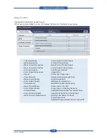
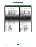
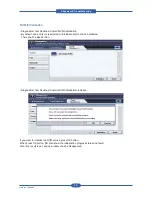
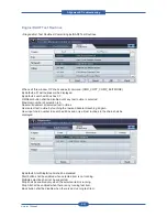
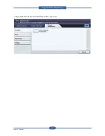
• Engine Diagnostic Contol(EDC) Menu
0~4
Reserved
5
DADF
6~19
Reserved
20
FAX
100
Engine(Motor)
101
Engine(Clutch & Actuator)
102
Engine(Paper Handling)
103
Engine(Timing)
104
Engine(Consumables)
105
Engine(Charger)
106
Engine(Developer)
107
Engine(Transfer)
108
Engine(Environment)
109
Engine(Fixing)
110
Engine(LSU)
111
Engine(Toner)
112
Engine(ACR)
113
Engine(Option/Finisher)
114
Engine(Option/SCF)
115
Engine(Option/Reserved)
116
Engine(Option/Reserved)
117
Engine(CTD)
118~255
Reserved
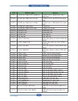
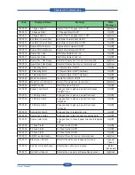
Code
Displayed Name
Meaning
State
Displayed
100-0000
Main BLDC Motor
Main BLDC Motor is On/Off
On[Off]
100-0001
Main BLDC Motor Ready
Detect if Main BLDC Motor runs at normal speed
High[Low]
100-0002
Black OPC/DEV Motor
Black OPC/DEV BLDC Motor is On/Off
On[Off]
100-0003
Black OPC/DEV Motor
Ready
Detect if Black OPC/DEV BLDC Motor runs at
normal speed
High[Low]
100-0004
Color OPC Motor
Color OPC BLDC Motor is On/Off
On[Off]
100-0005
Color OPC Motor Ready
Detect if Color DEV BLDC Motor runs at normal
speed
High[Low]
100-0006
Color DEV Motor
Color DEV BLDC Motor is On/Off
On[Off]
100-0007
Color DEV Motor Ready
Detect if Color DEV BLDC Motor runs at normal
speed
High[Low]
100-0008
T1 Engage Motor
T1 Engage Motor On/Off
On[Off]
Summary of Contents for MFX-C4000
Page 2: ......
Page 14: ...Precautions Service Manual 1 6 ...
Page 35: ...Service Manual 2 21 Video Controller Power Distribution Product Specifications and Features ...
Page 37: ...Service Manual 2 23 Engine Controller Power Distribution Product Specifications and Features ...
Page 39: ...Service Manual 2 25 DADF Block Diagram Product Specifications and Features ...
Page 106: ...Maintenance and Disassembly Service Manual 3 44 ...
Page 216: ...Alignment Troubleshooting Service Manual 4 110 ...
Page 217: ...System Diagram Service Manual 5 1 5 System Diagram 5 1 Block Diagram 5 1 1 System ...
Page 218: ...System Diagram Service Manual 5 2 5 1 2 Video Controller ...
Page 219: ...System Diagram Service Manual 5 3 5 1 3 Engin Controller ...
Page 220: ...System Diagram Service Manual 5 4 5 1 4 OPE Unit ...
Page 221: ...System Diagram Service Manual 5 5 5 1 5 DADF ...
Page 222: ...System Diagram Service Manual 5 6 5 1 6 SCF HCF ...
Page 225: ...System Diagram Service Manual 5 9 5 2 3 OPE Unit ...
Page 226: ...System Diagram Service Manual 5 10 5 2 4 DADF ...
Page 227: ...System Diagram Service Manual 5 11 5 2 5 SCF HCF ...
Page 228: ...System Diagram Service Manual 5 12 ...
Page 237: ...Reference Information Service Manual 6 9 ...
Page 238: ...Reference Information Service Manual 6 10 ...
Page 239: ...Reference Information Service Manual 6 11 ...
Page 240: ...Reference Information Service Manual 6 12 ...
Page 279: ......


