Service Manual
2-20
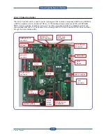
2.3.2.1 Video Controller
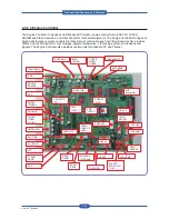
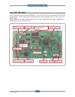
The Video Controller which is used to control printing and FAX functions comprises a MIPS core (RM7965),
a MIPS-companion video controller (SPGPxm), a PCI-interfaced image processor (CIP5) with SDRAMs,
DDR1 memory modules, and Flash memories. The Video controller includes an embedded network and
also provides USB host 2.0. The Scanner Part including DADF & CCD is connected to the Video controller
through the Scan Interface PBA.
SCAN IF
connector
Engine B’d IF
connector
USB HOST
USB
Device
N/W connector
CIP5(IP)
HDD(SATA)
power connector
OPE main
connector
HDD(SATA) IF
connector
OPE USB I/F
connector
FDI
connector
DDR1 Option
DIMM Slot
CPU
SPGPxm
DDR1
BASE
DIMM
RM7965(MIPS)
LIU IF
Scanner
SDRAM
SCAN IF
connector
Engine B’d IF
connector
CIP5(IP)
DDR1 Option
DIMM Slot
CPU
SPGPxm
DDR1
BASE
DIMM
RM7965(MIPS)
LIU IF
Scanner
SDRAM
Product
S
pec
ifications
and
F
eature
s
Summary of Contents for MFX-C4000
Page 2: ......
Page 14: ...Precautions Service Manual 1 6 ...
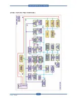
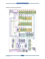
Page 35: ...Service Manual 2 21 Video Controller Power Distribution Product Specifications and Features ...
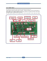
Page 37: ...Service Manual 2 23 Engine Controller Power Distribution Product Specifications and Features ...
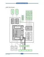
Page 39: ...Service Manual 2 25 DADF Block Diagram Product Specifications and Features ...
Page 106: ...Maintenance and Disassembly Service Manual 3 44 ...
Page 216: ...Alignment Troubleshooting Service Manual 4 110 ...
Page 217: ...System Diagram Service Manual 5 1 5 System Diagram 5 1 Block Diagram 5 1 1 System ...
Page 218: ...System Diagram Service Manual 5 2 5 1 2 Video Controller ...
Page 219: ...System Diagram Service Manual 5 3 5 1 3 Engin Controller ...
Page 220: ...System Diagram Service Manual 5 4 5 1 4 OPE Unit ...
Page 221: ...System Diagram Service Manual 5 5 5 1 5 DADF ...
Page 222: ...System Diagram Service Manual 5 6 5 1 6 SCF HCF ...
Page 225: ...System Diagram Service Manual 5 9 5 2 3 OPE Unit ...
Page 226: ...System Diagram Service Manual 5 10 5 2 4 DADF ...
Page 227: ...System Diagram Service Manual 5 11 5 2 5 SCF HCF ...
Page 228: ...System Diagram Service Manual 5 12 ...
Page 237: ...Reference Information Service Manual 6 9 ...
Page 238: ...Reference Information Service Manual 6 10 ...
Page 239: ...Reference Information Service Manual 6 11 ...
Page 240: ...Reference Information Service Manual 6 12 ...
Page 279: ......


