Alignment & Troubleshooting
Service Manual
4-79
Problem Description
Cause Description
Action to Resolve
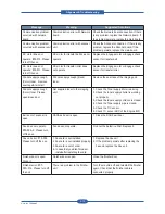
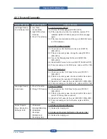
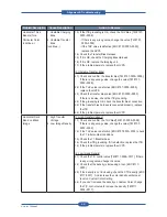
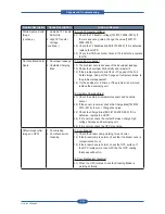
Vertical Irregular
Image Density for All
Colors
1. Unbalanced T2
Transfer
[1. Unbalanced T2 Transfer]
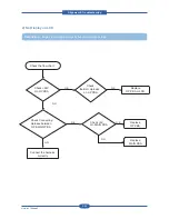
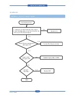
1.1) Check the THV value.[EDC #107-0005] If there is any
wrong value, replace the HVPS
1.2) Check the T2 Engage/Disenage Motoer[EDC #100-0010].
If it is defective, replace the T2 Engage Motor.
1.3) Check the T2 Engage/Disenage sensor [#EDC #100-0011].
If it is defective, replace the sensor.
1.4) When checking T2 Engage/Disenage [#EDC #100-0010],
check that the T2 Roller work or not. If not work, replace
the T2 Unit.
1.5) Check the ITB Drive Roller Ground. If it is defective, replace
the ITB.
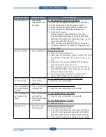
Image Density
Difference between
Right and Left Sides
for a Particular Color
1. Unbalanced T1
Transfer Roller Nip
[1. Unbalanced T1 Transfer Roller Nip]
1.1) Check that the Front Cover is locking properly.
1.2) Take out the ITB and check the T1 roller state. If it is
defective, replace the ITB.
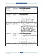
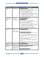
Image Density
Difference between
Right and Left Sides
for All Colors
1. Unbalanced T2
Transfer Roller Nip
[1. Unbalanced T2 Transfer Roller Nip]
1.1) Check that the Side Cover is locking properly.
1.2) Check the T2 Engage/Disenage Motoer[EDC #100-0010].
If it is defective, replace the T2 Engage Motor.
1.3) Check the T2 Engage/Disenage sensor [#EDC #100-0011].
If it is defective, replace the sensor.
1.4) When checking T2 Engage/Disenage [#EDC #100-0010],
check that the T2 Roller work or not. If not work, replace
the T2 Unit.
1.5) Check the ITB Drive Roller Ground. If it is defective, replace
the ITB.
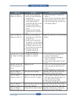
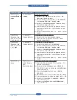
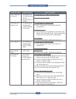
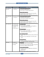
Horizontal White
Line(s)
1. Mis-Contact on T1
and/or Charging
Bias
2. Electrostatic Noise
[1. Mis-Contact on T1 and/or Charging Bias]
1.1) Take out the ITB and check the T1 roller conditions. If it is
defective, replace the ITB.
1.2) Check and confirm MHV Bias for the color [TM #105-
0010~0016]. If there is any wrong value, change the value
[TM #105-0010~0016].
1.3) Turn on the Charging Bias for the color [EDC #105-
0000~0003]
1.4) Read the MHV value for the color [EDC #105-0004~0007]
1.5) If any mis-reading on the MHV value, replace HVPS-L PBA.
1.6) Check the OPC grounding. If the grounding is defective,
replace the Imaging unit.
1.7) Check the ITB grounding. If the grounding is defective,
replace the ITB unit.
Summary of Contents for MFX-C4000
Page 2: ......
Page 14: ...Precautions Service Manual 1 6 ...
Page 35: ...Service Manual 2 21 Video Controller Power Distribution Product Specifications and Features ...
Page 37: ...Service Manual 2 23 Engine Controller Power Distribution Product Specifications and Features ...
Page 39: ...Service Manual 2 25 DADF Block Diagram Product Specifications and Features ...
Page 106: ...Maintenance and Disassembly Service Manual 3 44 ...
Page 216: ...Alignment Troubleshooting Service Manual 4 110 ...
Page 217: ...System Diagram Service Manual 5 1 5 System Diagram 5 1 Block Diagram 5 1 1 System ...
Page 218: ...System Diagram Service Manual 5 2 5 1 2 Video Controller ...
Page 219: ...System Diagram Service Manual 5 3 5 1 3 Engin Controller ...
Page 220: ...System Diagram Service Manual 5 4 5 1 4 OPE Unit ...
Page 221: ...System Diagram Service Manual 5 5 5 1 5 DADF ...
Page 222: ...System Diagram Service Manual 5 6 5 1 6 SCF HCF ...
Page 225: ...System Diagram Service Manual 5 9 5 2 3 OPE Unit ...
Page 226: ...System Diagram Service Manual 5 10 5 2 4 DADF ...
Page 227: ...System Diagram Service Manual 5 11 5 2 5 SCF HCF ...
Page 228: ...System Diagram Service Manual 5 12 ...
Page 237: ...Reference Information Service Manual 6 9 ...
Page 238: ...Reference Information Service Manual 6 10 ...
Page 239: ...Reference Information Service Manual 6 11 ...
Page 240: ...Reference Information Service Manual 6 12 ...
Page 279: ......


