Alignment & Troubleshooting
Service Manual
4-43
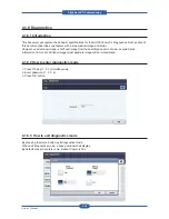
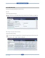
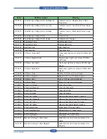
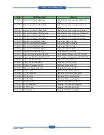
Usage Counter
• Diagnostics>Information>Usage Counter
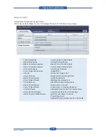
• When user selects Usage Counter, OP displays the amount of the Items shown below.
• Total Impressions
• Black Impressions
• Black Copied Impressions
• Black Printed Impressions
• Color Impressions
• Color Copied Impressions
• Sheets
• Copied Sheets
• Black Copied Sheets
• Color Copied Sheets
• Printed Sheets
• Black Printed Sheets
• Color Printed Sheets
• 2 Sided Sheets
• Copied 2 Sided Sheets
• Black Copied 2 Sided Sheets
• Color Copied 2-Sided Sheets
• Printed 2 Sided Sheets
• Black Printed 2 Sided Sheets
• Color Printed 2 Sided Sheets
• Fax Images Received
• Images Sent
• Server Fax Images Sent
• Network Scanning Images Sent
• Email Images Sent
• Maintenance Impressions
• Black Maintenance Impressions
• Known Jams in the IOT
• Known Jams in Finishing Device(s)
• Attempted Sheet Feeds from Internal trays
• Actual sheet feeds from Internal trays
• Normal Level Power On Hours
• Power Save Hours
• Attempted Original Sheet Feeds in the DADF
Summary of Contents for MFX-C4000
Page 2: ......
Page 14: ...Precautions Service Manual 1 6 ...
Page 35: ...Service Manual 2 21 Video Controller Power Distribution Product Specifications and Features ...
Page 37: ...Service Manual 2 23 Engine Controller Power Distribution Product Specifications and Features ...
Page 39: ...Service Manual 2 25 DADF Block Diagram Product Specifications and Features ...
Page 106: ...Maintenance and Disassembly Service Manual 3 44 ...
Page 216: ...Alignment Troubleshooting Service Manual 4 110 ...
Page 217: ...System Diagram Service Manual 5 1 5 System Diagram 5 1 Block Diagram 5 1 1 System ...
Page 218: ...System Diagram Service Manual 5 2 5 1 2 Video Controller ...
Page 219: ...System Diagram Service Manual 5 3 5 1 3 Engin Controller ...
Page 220: ...System Diagram Service Manual 5 4 5 1 4 OPE Unit ...
Page 221: ...System Diagram Service Manual 5 5 5 1 5 DADF ...
Page 222: ...System Diagram Service Manual 5 6 5 1 6 SCF HCF ...
Page 225: ...System Diagram Service Manual 5 9 5 2 3 OPE Unit ...
Page 226: ...System Diagram Service Manual 5 10 5 2 4 DADF ...
Page 227: ...System Diagram Service Manual 5 11 5 2 5 SCF HCF ...
Page 228: ...System Diagram Service Manual 5 12 ...
Page 237: ...Reference Information Service Manual 6 9 ...
Page 238: ...Reference Information Service Manual 6 10 ...
Page 239: ...Reference Information Service Manual 6 11 ...
Page 240: ...Reference Information Service Manual 6 12 ...
Page 279: ......

