Alignment & Troubleshooting
Service Manual
4-23
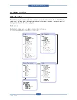
4.1.6 Menu overview
4.1.6.1 Menu Map
The control panel provides access to various menus to set up the machine or use the machine’s functions.
These menus can be accessed by pressing
Machine Setup,
Job Status or touching menus on the
display screen. Refer to the following diagram.
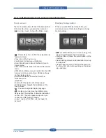
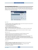
Main screen
The Main screen is shown on the display screen on the control panel.
Some menus are grayed out depending on your model.
Co
py
Basic
tab
Original Size
Reduce/Enlarge
Duplex
Output
Original T
yp
e
Darkness
Pap
er Supply
Advanced
tab
ID
Copy
N-Up
Poster Cop
y
Clone Co
py
Book Copy
Booklet
Covers
Transparencies
Image
tab
Erase Edge
Erase Background
Ma
rgin Shift
Fax
(Optional)
Basic
tab
Address
Duplex
Resolution
Advanced
tab
Original Size
De
lay
Send
Prio
rity Sen
d
Polling
Ma
ilbox
Image
tab
Original T
yp
e
Darkness
Erase Background
Color
Mode
Scan
Scan to Email
Basic
tab
Advanced
tab
Image
tab
Output
tab
NetScan
Basic
tab
Advanced
tab
Image
tab
Output
tab
Scan to Server
Basic
tab
Advanced
tab
Image
tab
Output
tab
Stored Documents
Public
tab
Detail
Edit
Delete
Delete All
Secured
tab
Detail
Edit
Delete
USB
USB Format
USB Print
Scan to USB
Basic
tab
Advanced
tab
Image
tab
Output
tab
Summary of Contents for MFX-C4000
Page 2: ......
Page 14: ...Precautions Service Manual 1 6 ...
Page 35: ...Service Manual 2 21 Video Controller Power Distribution Product Specifications and Features ...
Page 37: ...Service Manual 2 23 Engine Controller Power Distribution Product Specifications and Features ...
Page 39: ...Service Manual 2 25 DADF Block Diagram Product Specifications and Features ...
Page 106: ...Maintenance and Disassembly Service Manual 3 44 ...
Page 216: ...Alignment Troubleshooting Service Manual 4 110 ...
Page 217: ...System Diagram Service Manual 5 1 5 System Diagram 5 1 Block Diagram 5 1 1 System ...
Page 218: ...System Diagram Service Manual 5 2 5 1 2 Video Controller ...
Page 219: ...System Diagram Service Manual 5 3 5 1 3 Engin Controller ...
Page 220: ...System Diagram Service Manual 5 4 5 1 4 OPE Unit ...
Page 221: ...System Diagram Service Manual 5 5 5 1 5 DADF ...
Page 222: ...System Diagram Service Manual 5 6 5 1 6 SCF HCF ...
Page 225: ...System Diagram Service Manual 5 9 5 2 3 OPE Unit ...
Page 226: ...System Diagram Service Manual 5 10 5 2 4 DADF ...
Page 227: ...System Diagram Service Manual 5 11 5 2 5 SCF HCF ...
Page 228: ...System Diagram Service Manual 5 12 ...
Page 237: ...Reference Information Service Manual 6 9 ...
Page 238: ...Reference Information Service Manual 6 10 ...
Page 239: ...Reference Information Service Manual 6 11 ...
Page 240: ...Reference Information Service Manual 6 12 ...
Page 279: ......

