Alignment & Troubleshooting
Service Manual
4-16
4.1.3 Abnormal Image Printing and Defective Roller
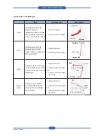
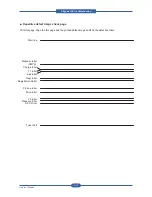
If a mark or other printing defect occurs at regular intervals down the page, it may be caused by a damaged
or contaminated roller. Make sure the repetition interval by consulting the table below.
If the roller is dirty, try to clean it. If the problem is still occurred after cleaning the roller, replace the part
including the defective roller.
NO
Roller
Period
(mm)
Phenomenon
Replace part
1
Pressure Roller
91.1
Offset, Spot, Line Burst
Fuser Unit
2
T2 Roller
88.0
White and Black Spot, Periodic Banding,
Rear Side Paper Dirty
Transfer Roller
3
Registration Roller
59.7
Roll Mark
-
4
Pick-up Roller
72.3
Roll Mark
-
5
Drive Roller
77.8
Periodic Banding, Color Registration
ITB Unit
6
T1 Roller
44.0
White and Black Spot, Periodic Banding
ITB Unit
7
Exit Roller
47.1
Roll Mark, Vertical Scratch
-
8
OPC Drum
94.3
White and Black Spot, Periodic Banding,
Ghost, Color Registration
Imaging Unit
Charger Roller
44.0
White and Black Spot, Periodic Banding
Imaging Unit
Magnetic Roller (K)
35.3
Periodic Banding
Imaging Unit
Magnetic Roller
(YMC)
35.3
Periodic Banding
Imaging Unit
9
Fuser Belt
127.7
Waving, Offset, Spot, Line Burst
Fuser Unit
10
ITB
785.4
White and Black Spot, Periodic Banding
ITB Unit
Summary of Contents for MFX-C4000
Page 2: ......
Page 14: ...Precautions Service Manual 1 6 ...
Page 35: ...Service Manual 2 21 Video Controller Power Distribution Product Specifications and Features ...
Page 37: ...Service Manual 2 23 Engine Controller Power Distribution Product Specifications and Features ...
Page 39: ...Service Manual 2 25 DADF Block Diagram Product Specifications and Features ...
Page 106: ...Maintenance and Disassembly Service Manual 3 44 ...
Page 216: ...Alignment Troubleshooting Service Manual 4 110 ...
Page 217: ...System Diagram Service Manual 5 1 5 System Diagram 5 1 Block Diagram 5 1 1 System ...
Page 218: ...System Diagram Service Manual 5 2 5 1 2 Video Controller ...
Page 219: ...System Diagram Service Manual 5 3 5 1 3 Engin Controller ...
Page 220: ...System Diagram Service Manual 5 4 5 1 4 OPE Unit ...
Page 221: ...System Diagram Service Manual 5 5 5 1 5 DADF ...
Page 222: ...System Diagram Service Manual 5 6 5 1 6 SCF HCF ...
Page 225: ...System Diagram Service Manual 5 9 5 2 3 OPE Unit ...
Page 226: ...System Diagram Service Manual 5 10 5 2 4 DADF ...
Page 227: ...System Diagram Service Manual 5 11 5 2 5 SCF HCF ...
Page 228: ...System Diagram Service Manual 5 12 ...
Page 237: ...Reference Information Service Manual 6 9 ...
Page 238: ...Reference Information Service Manual 6 10 ...
Page 239: ...Reference Information Service Manual 6 11 ...
Page 240: ...Reference Information Service Manual 6 12 ...
Page 279: ......

