Alignment & Troubleshooting
Service Manual
4-41
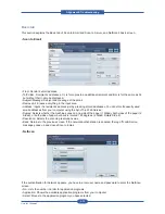
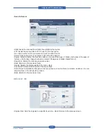
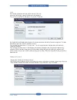
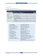
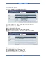
• User Behavior
- User can select one item in the list to reset the counter using “Reset” button or to edit the Max.Life and
threshold value using “Edit” button.
• Items in this column are:
DADF Roller / Rubber Pad Life Page
T1/T2/T3 P-up Roller Life Page
Retard Roller Life Page
Bypass Rubber Pad Life page
Transfer Roller Life Page
Fuser Roller / Fuser Unit Life Page
Heat Roller Life Page
Pressure Roller Life Page
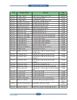
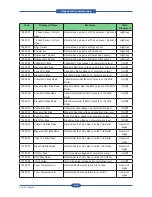
• Status
- The possible values in this column are ‘OK’, ‘Check’, ‘Negative’ and ‘Off’.
- OK : Actual counter is smaller than the threshold value
- Check : Actual counter is bigger than threshold value but smaller than Max.Life
- Off : Actual counter exceeds Max.Life
- Negative : There is no counter to display. In this case, it shall display ‘-‘ in the
Status and Max Life column.
• Actual
- Values in this column are actual counts for HFSI usage
• Max. Life
Values in this column are maximum life limits set for HFSI.
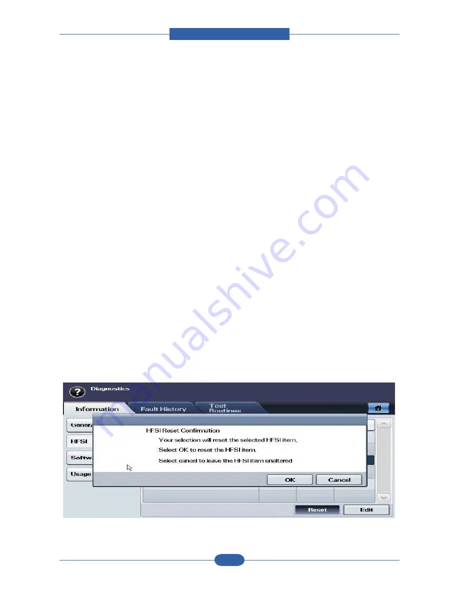
• Reset
This button is used to reset the actual counter after replacing the HFSI unit.
This button is disabled before user select one item in the list and enabled once user select any of the items
in the list.
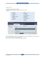
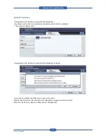
Once user presses, a confirmation window shall display to user confirm again. The window is displayed as
below.
If user confirms reset, it will reset the counter to 0.
If the counter of selected item is 0, ‘Reset’ button shall be disabled.
Summary of Contents for MFX-C4000
Page 2: ......
Page 14: ...Precautions Service Manual 1 6 ...
Page 35: ...Service Manual 2 21 Video Controller Power Distribution Product Specifications and Features ...
Page 37: ...Service Manual 2 23 Engine Controller Power Distribution Product Specifications and Features ...
Page 39: ...Service Manual 2 25 DADF Block Diagram Product Specifications and Features ...
Page 106: ...Maintenance and Disassembly Service Manual 3 44 ...
Page 216: ...Alignment Troubleshooting Service Manual 4 110 ...
Page 217: ...System Diagram Service Manual 5 1 5 System Diagram 5 1 Block Diagram 5 1 1 System ...
Page 218: ...System Diagram Service Manual 5 2 5 1 2 Video Controller ...
Page 219: ...System Diagram Service Manual 5 3 5 1 3 Engin Controller ...
Page 220: ...System Diagram Service Manual 5 4 5 1 4 OPE Unit ...
Page 221: ...System Diagram Service Manual 5 5 5 1 5 DADF ...
Page 222: ...System Diagram Service Manual 5 6 5 1 6 SCF HCF ...
Page 225: ...System Diagram Service Manual 5 9 5 2 3 OPE Unit ...
Page 226: ...System Diagram Service Manual 5 10 5 2 4 DADF ...
Page 227: ...System Diagram Service Manual 5 11 5 2 5 SCF HCF ...
Page 228: ...System Diagram Service Manual 5 12 ...
Page 237: ...Reference Information Service Manual 6 9 ...
Page 238: ...Reference Information Service Manual 6 10 ...
Page 239: ...Reference Information Service Manual 6 11 ...
Page 240: ...Reference Information Service Manual 6 12 ...
Page 279: ......

