Alignment & Troubleshooting
Service Manual
4-42
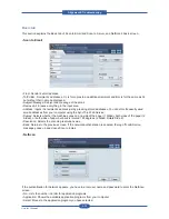
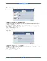
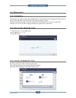
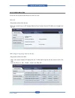
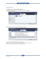
• Edit
“Edit” button is disabled until user select one item in the list.
Selecting “Edit” button causes edit window to be displayed.
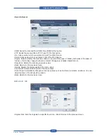
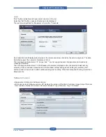
There are two input filed for ‘Maximum Life’ and for ‘Threshold’.
Each data field shall display default value or the last-saved value entered by the service engineer. The data
field shall support the numeric characters of 0 to 9.
The hard keypad characters of ‘#’, ‘phone’ and ‘*’ are not supported and shall generate an invalid entry
message if selected.
The hard keypad characters of ‘c’ shall delete all characters displayed within the selected data field. By
selecting ‘Cancel’, window moves back to HSFI window without saving user’s setting. By selecting ‘OK’
button, window moves back to HSFI window saving user’s setting. Threshold value shall not be greater than
Maximum Life.
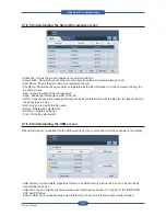
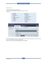
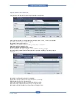
Software Version
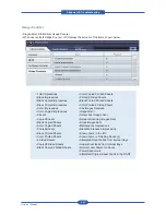
• Diagnostics>Information>Software Version
• When user selects Software version, OP displays the version of the Main Controller, Image Output Terminal,
User Interface, Network Controller, Document Feeder, Tray 2 Firmware, Tray 3 Firmware
Summary of Contents for MFX-C4000
Page 2: ......
Page 14: ...Precautions Service Manual 1 6 ...
Page 35: ...Service Manual 2 21 Video Controller Power Distribution Product Specifications and Features ...
Page 37: ...Service Manual 2 23 Engine Controller Power Distribution Product Specifications and Features ...
Page 39: ...Service Manual 2 25 DADF Block Diagram Product Specifications and Features ...
Page 106: ...Maintenance and Disassembly Service Manual 3 44 ...
Page 216: ...Alignment Troubleshooting Service Manual 4 110 ...
Page 217: ...System Diagram Service Manual 5 1 5 System Diagram 5 1 Block Diagram 5 1 1 System ...
Page 218: ...System Diagram Service Manual 5 2 5 1 2 Video Controller ...
Page 219: ...System Diagram Service Manual 5 3 5 1 3 Engin Controller ...
Page 220: ...System Diagram Service Manual 5 4 5 1 4 OPE Unit ...
Page 221: ...System Diagram Service Manual 5 5 5 1 5 DADF ...
Page 222: ...System Diagram Service Manual 5 6 5 1 6 SCF HCF ...
Page 225: ...System Diagram Service Manual 5 9 5 2 3 OPE Unit ...
Page 226: ...System Diagram Service Manual 5 10 5 2 4 DADF ...
Page 227: ...System Diagram Service Manual 5 11 5 2 5 SCF HCF ...
Page 228: ...System Diagram Service Manual 5 12 ...
Page 237: ...Reference Information Service Manual 6 9 ...
Page 238: ...Reference Information Service Manual 6 10 ...
Page 239: ...Reference Information Service Manual 6 11 ...
Page 240: ...Reference Information Service Manual 6 12 ...
Page 279: ......

