Page 50 MSI-3750CS RF Weighmeter • User Guide
3750CS
C
ELL
S
CALE RF DIGITAL WEIGHT INDICATOR
®
SET POINT STRING (SPSTRING)
Up to 20 characters are stored for each Set Point (1-32). These characters form the Set Point Message associated
with the current Set Point. This message is stored only in the 3750CS and is not programmable from the
CellScale Terminal Interface. Set Point “On” conditions transmitted from the CellScale will trigger local
3750CS message responses. The “SCREEN” and “SP OUTPUT” menus determine if and where the message
is sent. The message is sent only once per Set Point Transition. That is the Set Point must go false then true
again to regenerate the output message.
The 20 characters can include MSI “@ codes” that allow Set Points to include in their message such
characteristics of current weight, date, time, and any additional data required. This can form the basis
of a powerful maintenance tool. e.g. “Winch 1 overload 1/10/2002 23:00” which is generated with the
following string: “Winch1 overload@D1@T2”. Note that the printout is longer than 20 characters due
to the use of “@ Codes”.
Messages assigned to the LCD screen are not interpreted, therefore @ codes will display as written. Only
outputting the message to the RS-232 port will interpret the @ codes as shown in the example. Also messages
intended for the LCD are better written in all caps to make them easier to read on the message display. Messages
intended for the RS-232 output can mix any combination of characters and “@ codes”.
SCREEN
The screen menu determines the behavior of the 3750CS LCD Screen. Choices are: 1) Message – causes
either the Set Point String to scroll across the lower display when the Set Point is triggered on, or the Set
Point number will display. This is determined by the SP Output menu. If there are “@ Codes” embedded in
the SP String, they will not be interpreted and will display as written. 2) Normal – The LCD is not affected
by the Set Point. 3) Blank LCD – the weight display is blanked while the Set Point is true. 4) Blink – the
weight display blinks while the Set Point is true.
SET POINT OUTPUT (SP OUTPT)
This menu directs where the SP String message goes. Choices are Comport1 On or Off, and Display
On or Off.
TEST SET POINTS (TEST SP)
Lets the user override the limits checking and just turn on the Set Point. Use this for testing the effect of relay
closures and the formatting of printouts. It is usually best to disable all the Set Points with the “ALL SP” menu
before testing them. This prevents any interference from Set Points that may be triggered. The Test Set Points
routine cannot turn off triggered Set Points.
EXAMPLE SET POINT PROGRAMMING
Programming 32 Set Points takes careful planning. To assist in planning 1 to 32 Set Points see Appendix E.
Appendix E is a form that details all the capabilities of each of the 32 Set Points. Once planned, the entry of data,
using either the CellScale Terminal Interface or the 3750CS menus, is greatly simplified.
To program a Set Point from the 3750CS the following conditions must be met:
1) The CellScale must be on.
2) The 3750CS must be in communication with the CellScale.
3) A 3750CS function key must be set up for “Set Points”.
In the following examples, F2 is programmed for “SET POINTS”. If you use
another key, please adjust the procedure as necessary (see Section 4 “Function Keys”).
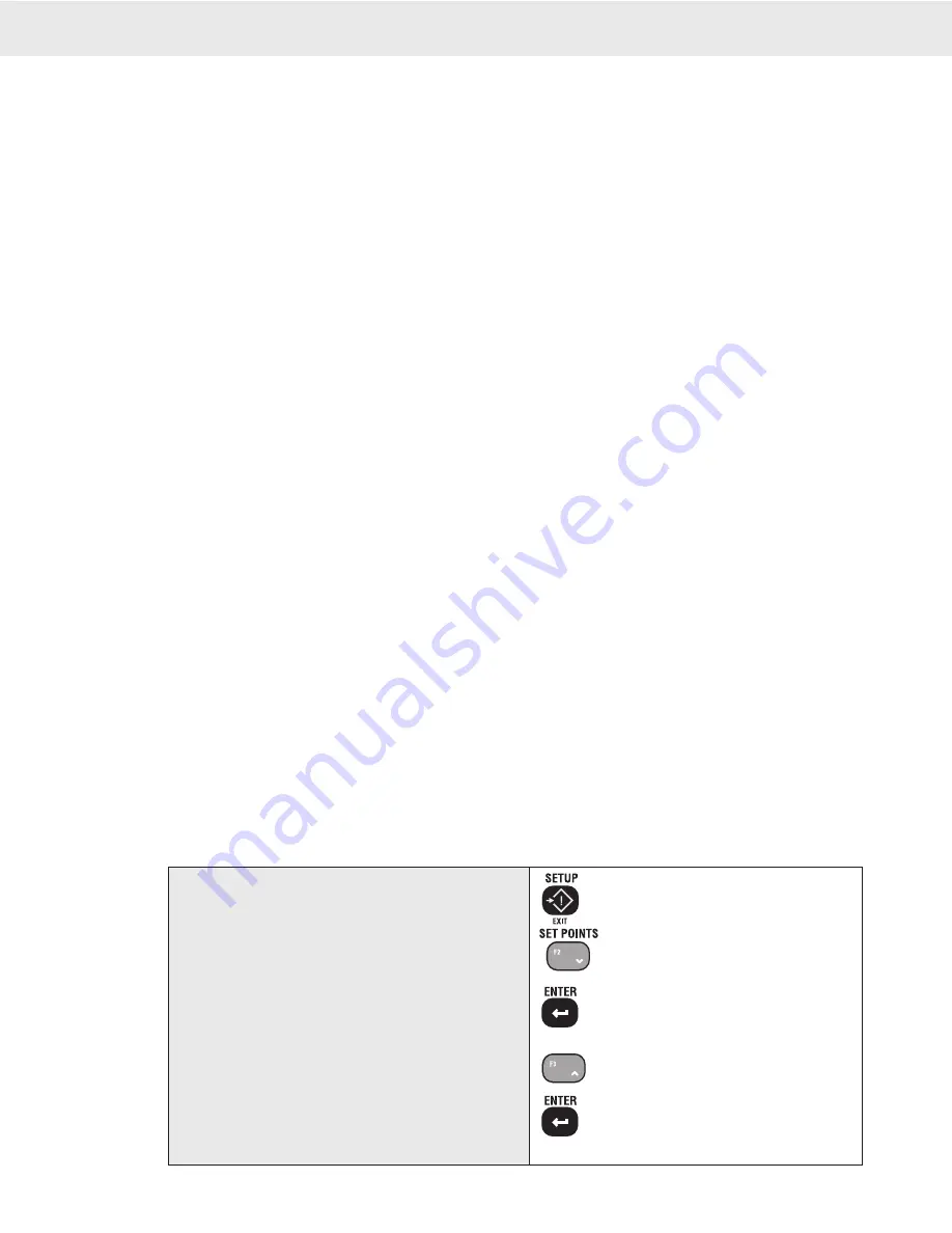
To Program a Single Threshold Set Point
1
SETUP
2
SETPOINT
3
ALL SP
4
CURNT SP
5
NEW SP
1) Push SETUP.
2) Push the SET POINTS key (F2 in our example).
The Menu reads “SETPOINT”.
3) Push ENTER. The first menu item will be “ALL
SP” which is the master Enable/Disable menu. We’ll
return to this later.
4) Push the UP key. The message reads “CURNT SP”
and the numberic display indicates the current Set
Point. For this example, we’re going to program
Set Point 2.
5) Push ENTER. The message reads “NEW SP”.


