Page 19
SYSTEM
Autofold Pro
SECTION E
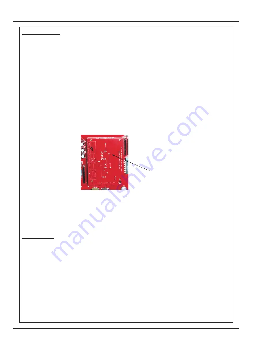
REPLACEMENT OF PROCESSOR BOARD.
REPLACEMENT OF USB FLASH DRIVE.
This Small PCB is plugged onto the face of the Main Control PCB and houses the Program
Chip.
The use of an antistatic wrist band should be used during work on this Processor PCB.
Switch the mains power off and disconnect from the mains supply.
Access is from the hinged Control Cover located beneath the feed bed. (see section on covers
for removal).
The USB Flash Drive controls all functions of the graphics and touch screen operation.
The External USB Flash Drive and the Internal USB Flash Drive devices (shown in FIG.2
below) have the same functionality. Either one of these devices could be supplied as a
replacement.
When fitting an Internal USB Flash Drive its orientation is important. Note the position of
the Lock Recess shown in FIG.2 below. The lock must also be in the unlocked position.
Ensure that the device fits securely and is fully inserted.
If the Internal Flash Drive is fitted the wrong way round it will not be damaged, it just won’t
work. Power down the machine and turn it round.
To remove care should be used, lifting from the bottom and gently rocking from side to side
seems to work the best.
Replacement is the reverse procedure, care should be taken that the correct orientation is
observed. (oscillator uppermost)
When changing the above board it may be necessary to recalibrate the machine.
Take note of any calibration settings prior to zeroing the count.
Note.
IMPORTANT!
Processor Board


