Page 16
SECTION D
Replacing the Touch Screen Assembly
Ensure the mains power is turned off but with the plug in the socket, this maintains an
earth to reduce static damage.
1. Open the hinged Lay Side Cover to expose the ITX board.
2. Unplug the USB connector and nine way “d” type plug from the ITX board, then
carefully remove the white power connector (this is tight and the wires can
easily be pulled from the plug)
3. Through the rear of the metal support loosen the two socket head screws using
a 4mm A/F Allen key. see below.
4. Carefully lift the unit up and through the top cover aperture.
Replacement is the opposite procedure.
Calibration of the Touch Screen.
1. Switch on the power and wait for the main screen to appear before commencing
to check the horizontal and vertical position of the display.
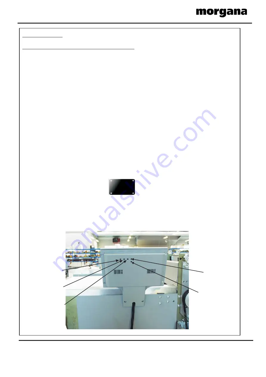
The position of the display within the surround is achieved by operating the
centre button at the rear of the housing, press this a number of times to obtain
the correct orientation required, move to the next button to move the position to
centralize horizontal.
2. Select the tools menu tab, and then select the Touch Screen calibration icon.
Using a plastic pointer, soft leaded pencil, biro cap etc. and with gentle pressure.
Touch the centre of the cross in each corner of the Touch Screen, as prompted, by
the hand graphics. This procedure will calibrate the Touch Screen.
Brightness
Contrast
Horizontal
Vertical
Brightness
Contrast
Horizontal
Vertical
UP
(Increase value)
UP
(Increase value)
DOWN
(Decrease value)
DOWN
(Decrease value)
Display
ON/OFF)
Display
ON/OFF)
AV / Display
Channel
AV / Display
Channel
FOLDING


