3 - 31
3. LOAD SIDE ENCODER
1)
2)
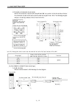
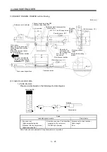
MR-EKCBL M-H
Cable model
1) CN2 connector
2) Junction connector
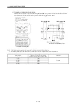
Connector set: 54599-1019
(Molex or equivalent)
MR-EKCBL M-H
View seen from wiring side.
(Note) Signal layout
1
P5
3
7
9
4
2
LG
8
6
10
5
MRR2
MR2
Note. Keep open the pins shown with
. Especially, pin 10 is provided for
manufacturer adjustment. If it is connected with any other pin, the
servo amplifier cannot operate normally.
Housing: 1-172161-9
Connector pin: 170359-1
(Tyco Electronics or equivalent)
Cable clamp: MTI-0002
(Toa Electric Industries)
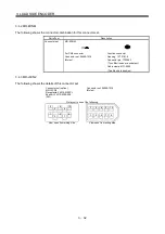
RQ
1
2
3
/RQ
4
5
6
P5
7
8
9
LG SHD
Signal layout
View seen from wiring side.
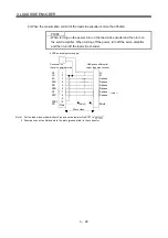
(3) Internal wiring diagram
P5
LG
1
2
MR2
MRR2
3
4
3
7
Servo amplifier side
Encoder side
9
SD
Plate
1
2
8
9
MR-EKCBL2M-H
MR-EKCBL5M-H
MR-EKCBL10M-H
LG
RQ
/RQ
SHD
P5
Summary of Contents for MR-J3-B-RJ006
Page 15: ...A 14 MEMO ...
Page 19: ...4 MEMO ...
Page 65: ...2 18 2 SIGNALS AND WIRING MEMO ...
Page 119: ...4 22 4 OPERATION AND FUNCTIONS MEMO ...
Page 145: ...6 6 6 TROUBLESHOOTING MEMO ...
Page 155: ...7 10 7 OUTLINE DRAWINGS MEMO ...
Page 165: ...SH NA 030056 C ...

