3 - 26
3. LOAD SIDE ENCODER
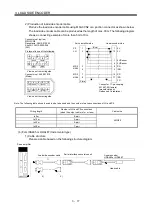
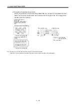
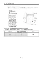
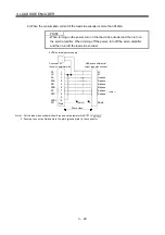
2) Production of load side encoder cable
Produce the load side encoder cable using MR-J3CN2 or a junction connector as shown below.
The load side encoder cable can be produced as the length of max. 30m.
1
3
MR2
7
9
4
MRR2
2
LG
8
6
10
5
P5
4
MRR2
2
LG
8
6
1
5
10
3
MR2
7
9
P5
Connector set: 54599-1019
(Molex)
View seen from wiring side.
Connector set (option)
MR-J3CN2
Receptacle: 36210-0100PL
Shell kit: 36310-3200-008
(3M)
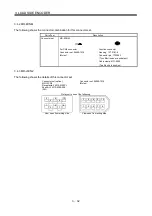
Pin layout is one of the following.
View seen from wiring side.
Connector: D-SUB (female) 15 pin
P5
LG
1
2
Servo amplifier side
Linear encoder side
SD
Plate
SD
/Q
/P
8
2
LG
P5
MR2
MR
3
4
10
1
MRR
MR
(Note 1) Limit switch output
Case
15 Inner
5
6
(Note2)
Note 1. A limit switch output signal can be connected. For details, contact with Renishaw Inc.
2. The following table shows the cable size to be used and the number of paired connections of LG and P5.
Wiring length
Number of LG and P5 connections
(when the output cable is 0.5m or less)
Cable size
to 5m
1-pair
to 10m
2-pair
to 20m
4-pair
to 30m
6-pair
AWG22
Summary of Contents for MR-J3-B-RJ006
Page 15: ...A 14 MEMO ...
Page 19: ...4 MEMO ...
Page 65: ...2 18 2 SIGNALS AND WIRING MEMO ...
Page 119: ...4 22 4 OPERATION AND FUNCTIONS MEMO ...
Page 145: ...6 6 6 TROUBLESHOOTING MEMO ...
Page 155: ...7 10 7 OUTLINE DRAWINGS MEMO ...
Page 165: ...SH NA 030056 C ...


