3 - 30
3. LOAD SIDE ENCODER
3.4 Mitsubishi optional cable connector sets
POINT
Protective structure indicated for cables and connecters is for a cable or
connector alone. When the cables and connectors are used to connect the
servo amplifier and servo motor, and if protective structures of the servo
amplifier and servo motor are lower than that of the cable and connector,
specifications of the servo amplifier and servo motor apply.
3.4.1 MR-EKCBL M-H
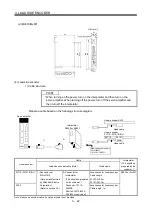
(1) Model explanations
Model
2
5
10
2
5
10
Symbol
Cable length [m]
Long flex life
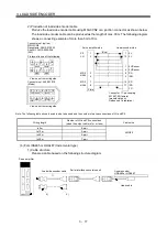
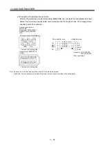
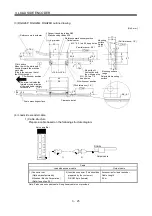
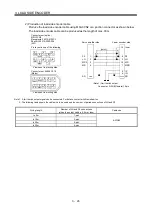
(2) Cable structure
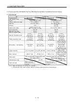
The table shows this optional cable structure.
Characteristics of one core
Protective
structure
Flex
life
Length
[m]
Core size
[mm
2
]
Number of
cores
Structure
[Wires/mm]
Conductor
resistance [ /mm]
Insulation coating
OD d [mm] (Note 1)
(Note 2)
Finishing OD
[mm]
Wire model
IP20 Long
flex
life
2 5 10 0.2mm
2
12
(6 pairs)
40/0.08 105
or
less
0.88
7.2
(Note 3)
A14B2339
6P
Note 1. d is as shown below.
d
Conductor Insulation sheath
2. Standard OD. Max. OD is about 10% greater.
3. Purchased from Toa Electric Industry.
Summary of Contents for MR-J3-B-RJ006
Page 15: ...A 14 MEMO ...
Page 19: ...4 MEMO ...
Page 65: ...2 18 2 SIGNALS AND WIRING MEMO ...
Page 119: ...4 22 4 OPERATION AND FUNCTIONS MEMO ...
Page 145: ...6 6 6 TROUBLESHOOTING MEMO ...
Page 155: ...7 10 7 OUTLINE DRAWINGS MEMO ...
Page 165: ...SH NA 030056 C ...


