2 - 12
2. SIGNALS AND WIRING
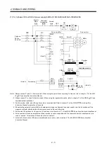
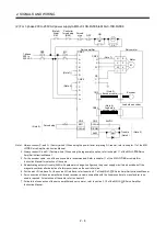
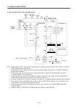
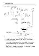
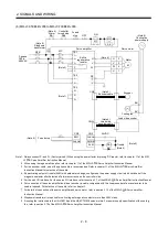
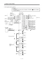
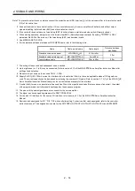
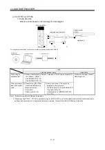
Note 1. Always connect P
1
and P. (Factory-wired.) When using the power factor improving DC reactor, refer to chapter 11 of the MR-J3-
B Servo Amplifier Instruction Manual.
2. Connect the regenerative resistor. When using a regenerative option for the MR-J3- B-RJ006 servo amplifier, refer to chapter
11 of the MR-J3- B-RJ006 Servo Amplifier Instruction Manual.
The regenerative resistor is not attached to the servo amplifiers of MR-J3-11KB(4)-RZ006 to MR-J3-22KB(4)-RZ006 as those of
MR-J3-11KB(4)-PX to MR-J3-22KB(4)-PX. Therefore, when using the regenerative option for MR-J3- B-RZ006 servo
amplifier, refer to section 11.2 (4) (d) MR-J3-11KB(4)-PX to MR-J3-22KB(4)-PX (when using the regenerative options) of the
MR-J3- B Servo Amplifier Instruction Manual.
3. The use of optional cable is recommended for the connection between the servo amplifier and servo motor. For the selection of
the cable, refer to chapter 11 of the MR-J3- B Servo Amplifier Instruction Manual.
4. If deactivating output of trouble (ALM) with parameter change, configure up the power supply circuit which switches off the
magnetic contactor after detection of alarm occurrence on the controller side.
5. For the sink I/O interface. For the source I/O interface, refer to chapter 3 of the MR-J3- B Servo Amplifier Instruction Manual.
6. For connection of the servo amplifier and linear encoder, a cable compatible with the linear encoder of a manufacturer to be
used is required. For selection of the cable, refer to chapter 3.
7. For details of connection of the servo amplifier and servo motor, refer to section 3.10 of the MR-J3- B Servo Amplifier
Instruction Manual.
8. Servo amplifiers does not have BW when the cooling fan power supply is 1-phase.
9. For the cooling fan power supply, refer to (3) (b) in section 3.10 of the MR-J3- B Servo Amplifier Instruction Manual.
10. Stepdown transformer is required for coil voltage of magnetic contactor more than 200V class.
Summary of Contents for MR-J3-B-RJ006
Page 15: ...A 14 MEMO ...
Page 19: ...4 MEMO ...
Page 65: ...2 18 2 SIGNALS AND WIRING MEMO ...
Page 119: ...4 22 4 OPERATION AND FUNCTIONS MEMO ...
Page 145: ...6 6 6 TROUBLESHOOTING MEMO ...
Page 155: ...7 10 7 OUTLINE DRAWINGS MEMO ...
Page 165: ...SH NA 030056 C ...

