6 - 4
6. TROUBLESHOOTING
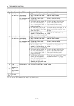
Display Name
Definition
Cause
Action
1. CN2L connector is disconnected.
Connect correctly.
2. Faulty of the load side encoder
cable
Repair or change the cable.
3. Wrong wiring of the load side
encoder cable
Review the wiring connection.
4. For the serial interface encoder, the
load side encoder cable type (2-
wire, 4-wire) selection was wrong in
the parameter setting.
Correct the setting in the fourth digit of
parameter No.PC26 (encoder cable
communication system selection).
5. The startup timing is slow.(For the
load side encoder with the external
power supply input)
Turn on the external power supply, and then
turn on the control power supply of servo
amplifier.
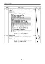
70 Load
side
encoder error 1
An error occurs in the
communication
between the load
side encoder and the
servo amplifier.
6. The power supply voltage
dropped.(For the load side encoder
with the external power supply input)
Check the power supply capacity and
voltage.
1. CN2L connector is disconnected.
Connect correctly.
2. Faulty of the load side encoder
cable
Repair or change the cable.
3. Wrong wiring of the load side
encoder cable
Review the wiring connection.
4. The power supply voltage
dropped.(For the load side encoder
with the external power supply input)
Check the power supply capacity and
voltage.
5. For the serial interface encoder, the
load side encoder cable type (2-
wire, 4-wire) selection was wrong in
the parameter setting.
Correct the setting in the fourth digit of
parameter No.PC26 (encoder cable
communication system selection).
71 Load
side
encoder error 2
An error occurs in the
communication
between the load
side encoder and the
servo amplifier.
6. For ABZ-phase input interface
encoder, the alarm judgement
without the Z-phase disconnection
was not set to “invalid” in the
parameter when using the load side
encoder without Z-phase.
For the load side encoder without Z-phase,
set parameter No.PC27 to " 1
".
8A USB
communication
time-out error
8E USB
communication
error
(Note)
888
Watchdog
Refer to chapter 8 of the MR-J3- B Servo Amplifier Instruction Manual.
Note. At power-on, "888" appears instantaneously, but it is not an error.
Summary of Contents for MR-J3-B-RJ006
Page 15: ...A 14 MEMO ...
Page 19: ...4 MEMO ...
Page 65: ...2 18 2 SIGNALS AND WIRING MEMO ...
Page 119: ...4 22 4 OPERATION AND FUNCTIONS MEMO ...
Page 145: ...6 6 6 TROUBLESHOOTING MEMO ...
Page 155: ...7 10 7 OUTLINE DRAWINGS MEMO ...
Page 165: ...SH NA 030056 C ...


