(7) Troubleshooting
(8) Maintenance, inspection and part replacement
CAUTION
Use a motor with electromagnetic brakes or
establish an external brake mechanism for the
purpose of holding; this serves as counter-
measures for possible hazardous situation
caused by power failure or product fault.
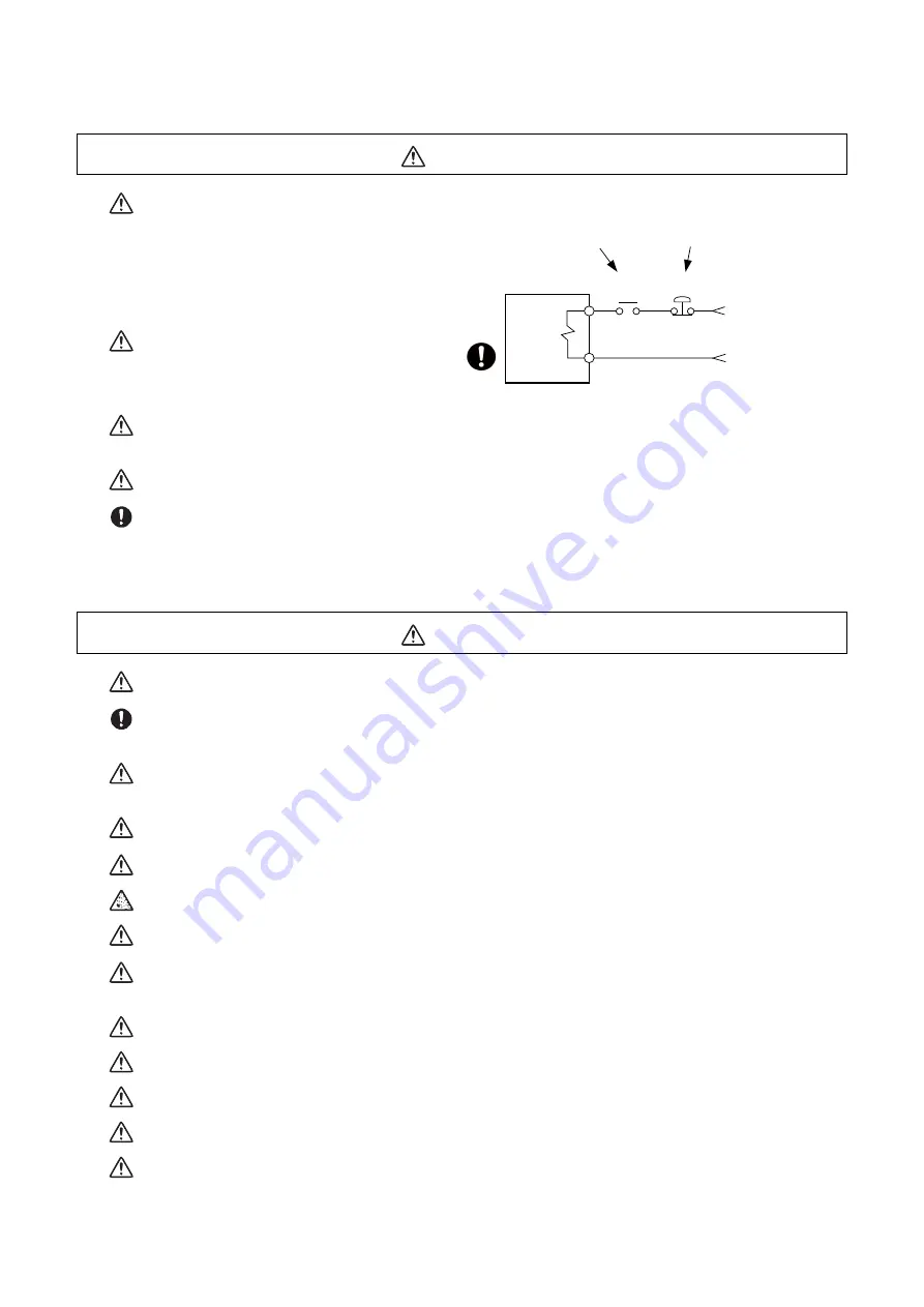
Use a double circuit structure for the electro-
magnetic brake's operation circuit so that the
brakes will activate even when the external
emergency stop signal is issued.
The machine could suddenly restart when the power is restored after an instantaneous power failure, so
stay away from the machine. (Design the machine so that the operator safety can be ensured even if the
machine restarts.)
To secure the absolute position, do not shut off the servo drive unit’s control power supply when its battery
voltage drops (warning 9F) in the servo drive unit side.
If the battery voltage drop warning alarm occurs in the controller side, make sure to back up the machining
programs, tool data and parameters, etc. with the input/output device before replacing the battery. Depend-
ing on the level of voltage drop, memory loss could have happened. In that case, reload all the data backed
up before the alarm occurrence.
CAUTION
Periodically back up the programs, tool data and parameters to avoid potential data loss. Also, back up
those data before maintenance and inspections.
When replacing the battery on the controller side, the machining programs, tool data and parameters
should be backed up with the input/output device beforehand. In case the memory is damaged in replacing
the batteries, reload all the data backed up before replacing the battery.
The electrolytic capacitor’s capacity will drop due to deterioration. To prevent secondary damage due to
capacitor's faults, Mitsubishi recommends the electrolytic capacitor to be replaced approx. every five years
even when used in a normal environment. Contact the Service Center for replacements.
Never perform a megger test (measure the insulation resistance) of the drive unit. Failure to observe this
could lead to faults.
Do not replace parts or devices while the power is ON.
Do not short-circuit, charge, overheat, incinerate or disassemble the battery.
There may be a unit filled with substitute Freon in the heat radiating fins of the 37kW or smaller unit. Be
careful not to break the heat radiating fins during maintenance or replacement.
Connect the encoder (CN2/CN3) immediately after the installation of the servo drive unit. In addition, when
a battery box is used, immediately connect to the BTA/BTB connector. (prevention of absolute position data
lost)
Replace the batteries with new ones immediately after the battery voltage drop alarm (9F) has been output.
Replace the batteries while applying the drive unit’s control power.
Replace the batteries with new ones that are in their recommended use period.
Wrong connection may cause liquid leakage, heat generation and/or explosion.
Do not mix new batteries with used ones or mix different types of batteries.
MBR
EMG
Motor
Electro-
magnetic
brake
Shut off with motor
brake control output
Shut off with CNC brake
control PLC output
24VDC
Summary of Contents for E80 Series
Page 1: ......
Page 7: ......
Page 17: ......
Page 19: ......
Page 21: ......
Page 23: ......
Page 25: ......
Page 28: ...1 1 IB 1501273 F System Basic Configuration ...
Page 68: ...2 41 IB 1501273 F Daily Maintenance and Periodic Maintenance ...
Page 78: ...3 51 IB 1501273 F Maintenance of the Drive Unit ...
Page 101: ...M800 M80 E80 Series Maintenance Manual 3 Maintenance of the Drive Unit 74 IB 1501273 F ...
Page 102: ...4 75 IB 1501273 F Failure Diagnosis ...
Page 165: ...M800 M80 E80 Series Maintenance Manual 4 Failure Diagnosis 138 IB 1501273 F ...
Page 166: ...5 139 IB 1501273 F Troubleshooting ...
Page 169: ...M800 M80 E80 Series Maintenance Manual 5 Troubleshooting 142 IB 1501273 F ...
Page 170: ...6 143 IB 1501273 F Replacing Each Unit ...
Page 205: ...M800 M80 E80 Series Maintenance Manual 6 Replacing Each Unit 178 IB 1501273 F ...
Page 212: ......


