background image

Lower Feeder Units (Trays 3 and 4)

158

17

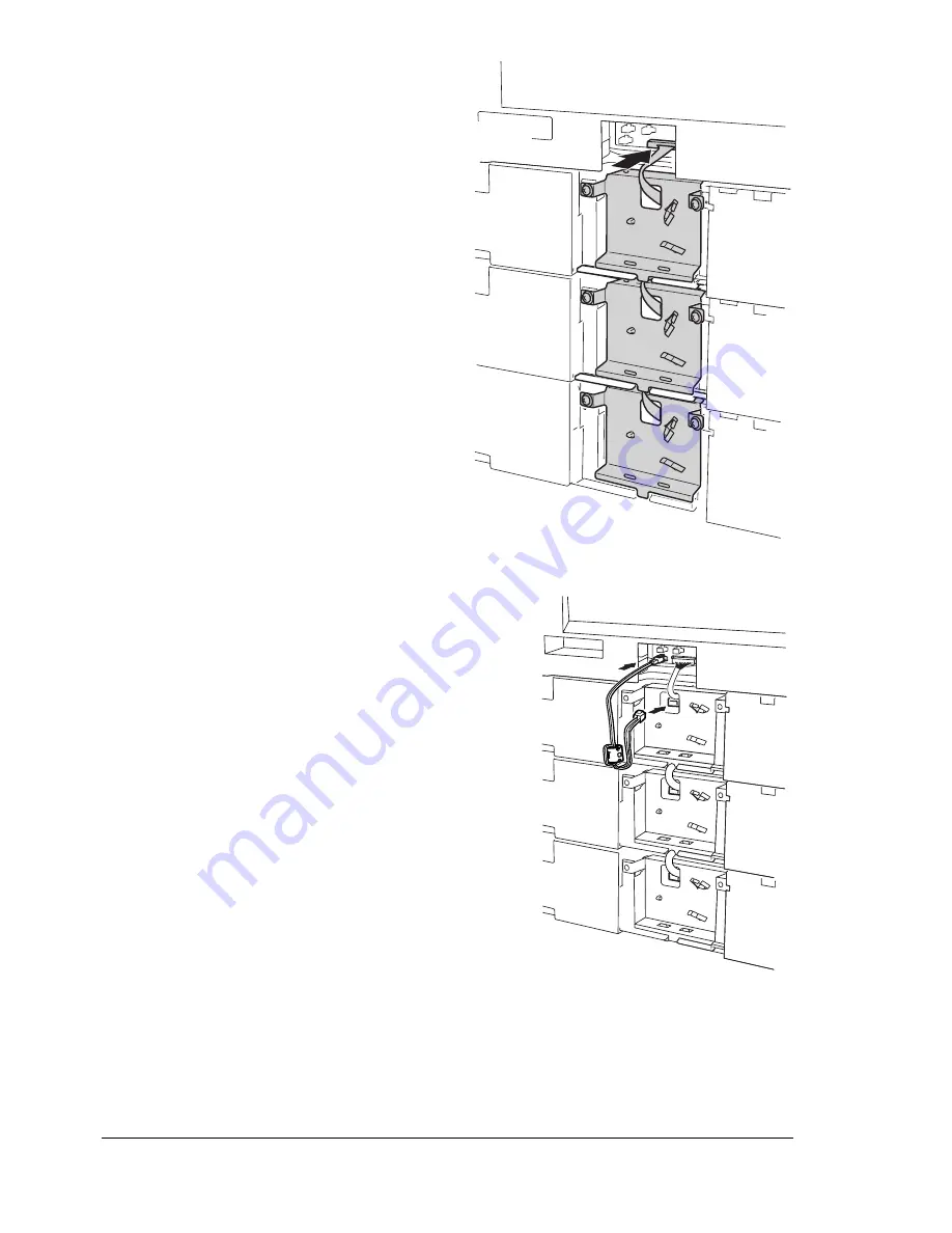
Connect the other end of the
control harness connected to
Tray 2’s upper connector to the
connector on the back of the
printer.

18

Plug the black 3-pin connector of power
supply harness A 
(with the core
attached) into a black socket at the
back of the printer, and then plug the
power supply harness A’s white 2-pin
connector into the white PJ6 socket on
Tray 2’s unit.

The 3-pin connector (black) can
be plugged into any of the three
sockets on the printer. As an
example, the illustration at the
right shows the connector
plugged into the lower-left
connector.

Summary of Contents for magicolor 7300

Page 1: ...magicolor 7300 User s Guide 1800698 001A...

Page 2: ...Inc Copyright Notice This guide is Copyrighted 2003 by MINOLTA QMS Inc One Magnum Pass Mobile AL 36618 All Rights Reserved This document may not be copied in whole or part nor transferred to any other...

Page 3: ...Installing Printer Drivers and Utilities Windows Environments Manual Instal lation 5 Installing Printer Drivers and Utilities Macintosh Environments 5 Some Notes to Consider 5 Macintosh OS 9 PPDs and...

Page 4: ...Control Panel LED Indicators 40 Control Panel Keys 42 Canceling Print Jobs 44 Printer Menu Overview 44 Menu Overview 44 Main Menu 46 Selecting a Message Window Language 46 Print Menu 47 Paper Menu 48...

Page 5: ...76 Environment 76 Opening the Status Monitor and Showing Supplies Status 76 Altering the Size of the Status Monitor Window 76 Using the Status Monitor 76 Recognizing Status Monitor Alerts 77 Recoverin...

Page 6: ...Duplex Unit 133 Installing the Manual Feed Tray 137 Uninstalling Duplex Unit Kit 139 Internal IDE Hard Disk Drive 144 Installing the Internal Hard Disk 144 Lower Feeder Units Trays 3 and 4 147 Kit Co...

Page 7: ...nical Specifications 211 Requirements 212 General 212 Controller 213 Electrical 214 Power Requirements 215 ENERGY STAR Compliance 216 Hazardous Chemical Substance Reporting 218 Physical 218 Space Requ...

Page 8: ...Contents vi...

Page 9: ...1 Software Installation...

Page 10: ...PPDs These PostScript Printer Description PPDs files can be used with third party Linux print filters that use PPDs Readme on the Software Utilities CD ROM Macintosh PPDs These PPD files allow you to...

Page 11: ...aces all needed print related components such as a PostScript Printer Description PPD file color profiles screen fonts and registration information in the correct locations on your system and allows y...

Page 12: ...hapter in the Reference Guide or PageScope Net Care Administrator s Manual both in PDF on the Software Utilities CD ROM Readme on the Software Utilities CD ROM PageScope Net Care Guide in the magicolo...

Page 13: ...r Drivers and Utilities Windows Environments Manual Installation Manual installation instructions are included in the magicolor 7300 Reference Guide on the Documentation CD ROM Refer to Section 2 Inst...

Page 14: ...ktop b Double click the Install icon c Follow the instructions on the screen to install the magicolor 7300 PPD and utilities d After the PPD and utilities installation is complete choose Quit e When t...

Page 15: ...e it on your Macintosh hard disk it can be found on your Macintosh s system CD ROM c Select Printer LPR and choose OK d Type in the IP address and use the same address for the Queue name Click OK e Ch...

Page 16: ...refer to the magicolor 7300 Reference Guide on the Documentation CD ROM Section 2 of the Reference Guide Installing Printer Software Drivers PPDs includes basic information about PDQ XPDQ CUPS and XPP...

Page 17: ...2 Using Media...

Page 18: ...What is the guaranteed imageable printable area page 13 How do I set page margins page 14 How can I change the image alignment page 14 Media Types How do I select the media type page 16 Printing Tray...

Page 19: ...x 900 M No Executive 7 25 x 10 5 184 x 267 LEF 1 Yes M No Folio A4 Plus 8 27 x 13 0 210 x 330 SEF 1 Yes M No Government Letter 8 0 x 10 5 203 x 267 LEF 1 Yes M No Government Legal 8 5 x 13 216 x 330 S...

Page 20: ...5 120 x 235 SEF 1 M Japanese Envelope Chokei 4 Chou 4 3 54 x 8 07 90 x 205 SEF 1 M Envelope Monarch 3 88 x 7 5 98 x 191 SEF 1 M Thick Stock Varies Varies 1 M Thick Stock 91 210 g m2 Notes LEF Long edg...

Page 21: ...dware limits the physical media size and the margins required by the printer and software constraints the amount of memory available for the full page frame buffer The guaranteed imageable printable a...

Page 22: ...format you may lose part of your image due to imageable area constraints If you can custom size your page in your application use those sizes given for the imageable area for optimum results How can I...

Page 23: ...ty Check www minolta qms com click on 24 Hour Online Help for currently approved media To order approved transparency media go to www q shop com Unsupported Media Do not use media that is Dusty Coated...

Page 24: ...thin or too thick Stuck together with static electricity Composed of foil or gilt or that is too luminous Heat sensitive or cannot withstand the fusing temperature 392 F 200 C Irregularly shaped not r...

Page 25: ...eeder unit trays Up to 500 sheets of 22 lb bond 80 g m2 paper letter A4 only each Manual Feed Tray 1 sheet at a time Orientation Trays 1 4 Face up Manual Feed Tray Face down Type Check www minolta qms...

Page 26: ...ly Do not use envelopes that have Sticky flaps Tape seals metal clasps paper clips fasteners or peel off strips for sealing Transparent windows Too rough of a surface Material that will melt vaporize...

Page 27: ...eets that Have labels that easily peel off Have the backing sheets that have peeled away or have exposed adhesive Labels may stick to the fuser causing them to peel off and media jams to occur Are pre...

Page 28: ...ed Manual Feed Tray One sheet at a time Orientation Tray 1 Face up Manual Feed Tray Face down Type Check www minolta qms com click on 24 Hour Online Help for currently approved media Driver Mode Postc...

Page 29: ...anual Feed Tray 1 sheet at a time Orientation Tray 1 Face up Manual Feed Tray Face down Type Check www minolta qms com click on 24 Hour Online Help for currently approved media Driver Mode Thick stock...

Page 30: ...Have as little static electricity as possible Do not use transparencies that Are designed for inkjet printers Are for oil fixing Capacity Tray 1 Up to 50 transparencies depending on their thickness Tr...

Page 31: ...type except plain paper Continuous printing on media other than plain paper such as envelopes labels thick stock or transparencies may adversely affect print quality or reduce engine life Do not mix m...

Page 32: ...ad and Memo Media 1 Slide out Tray 1 If you already have media in Tray 1 and want to change it remove the media from Tray 1 2 Press down on the media lifting plate until it locks Attention Be careful...

Page 33: ...Tray 1 7 In the printer driver select Plain Paper and the appropriate media size If you re using custom size media set the printer for custom sized media in the printer driver 8 Print the job Envelope...

Page 34: ...y Labels You can print continuously with label paper However this could affect the media feed depending on the media quality and printing environment If problems occur stop the continuous printing and...

Page 35: ...In the printer driver select Thick Stock and the appropriate size 4 Print the job Transparencies Format the information to be printed on the transparencies within your application Try printing your da...

Page 36: ...nt To improve stacking of transparencies put the media output tray extension in place before printing Trays 2 4 Only plain recycled letterhead or memo paper in sizes A3 A4 B4 B5 JIS 11 x 17 legal and...

Page 37: ...refully before loading it into the tray 3 Press down on the media lifting plate until it locks Attention Be careful not to touch the media pickup roller with your hands If the roller has been touched...

Page 38: ...e up print side Do not load media above the media limit mark 8 Slide the media guides against the edges of the loaded media Attention Always adjust the media guide after inserting the media A guide th...

Page 39: ...want to print on media not currently loaded into Trays 1 4 When printing using the manual feed tray insert only one sheet at a time The side facing down will be printed 1 Adjust the media guides for...

Page 40: ...Loading Media 32 Envelopes Postcards...

Page 41: ...QMS printer driver Default page sizes are set in inches on 110V printers and in millimeters on 220V printers When you set custom page sizes in 110V printers the two digits on the right are always deci...

Page 42: ...length equal or less than 17 inch 432 mm and with a width less than 11 7 inch 297 mm can be autoduplexed Memory Requirements Your printer comes configured with 128 MB of RAM Duplex printing can be don...

Page 43: ...river s Settings tab select Optional Duplexer in the Available Options box 2 Click Add The Optional Duplexer appears in the Installed Options box and duplex printing options are available in the print...

Page 44: ...ia type and the conditions of the operating environment media may fall out of the output tray If this occurs use the media stopper Remove transparencies as soon as possible from the output tray to avo...

Page 45: ...ht position Before using stored media do a trial printing and check print quality Additional Assistance Where can I order MINOLTA QMS approved media or get more information Check Check www minolta qms...

Page 46: ......

Page 47: ...3 Working with the Printer...

Page 48: ...ght keys allow you to control the printer configuration through access to frequently used printer functions Control Panel LED Indicators Number LED Indicator Off On 1 The printer is not ready to accep...

Page 49: ...mpanied by a status message in the message window 4 No problem The printer requires the operator s attention Accompanied by a status message in the message window 5 see also 6 below The printer is in...

Page 50: ...ter cannot be set to deep sleep mode when this key is pressed 7 Press this key to exit the configuration menu If a message appears asking for confirmation YES NO to perform some operations press this...

Page 51: ...12 Press this key to move down in the menu structure If within a selectable menu choice that can be changed character by character press this key to scroll downward through the available characters Wh...

Page 52: ...displays Printer Menu Overview Menu Overview Your printer has a comprehensive but easy to use menu system that allows you to change settings so they meet your print job s requirements All routine prin...

Page 53: ...ACE PARALLEL SYS DEFAULT 3 SYS DEFAULT LANGUAGE SYS DEFAULT ENERGY SAVER SYS DEFAULT BUZZER CONTROL SYS DEFAULT POSTSCRIPT SYS DEFAULT CHANGE PASSWORD SYS DEFAULT HDD FORMAT2 SYS DEFAULT CLOCK SYS DEF...

Page 54: ...and Spanish If you want to change the message window language use the following control panel sequence READY MAGICOLOR 7300 MAIN MENU PRINT MENU MAIN MENU PAPER MAIN MENU QUALITY MAIN MENU INTERFACE...

Page 55: ...om the Print menu paper from the tray specified with Default Tray is used The manufacturer s default setting is Tray1 Printing is generally possible on any size paper that is loaded however all of the...

Page 56: ...f an optional hard disk is installed Tray Chaining does not include the Manual Feed Tray Tray selection may be overridden by the printer driver PAPER INPUT TRAY DUPLEX COPIES COLLATE OFF SHORT EDGE LO...

Page 57: ...LIGNMENT ENABLE DISABLE TOP ADJ NORMAL TOP ADJ THICK LEFT ADJUST LEFT ADJ DUPLEX TRAY1 TRAY2 TRAY3 TRAY4 DUPLEX 2PASS MANUAL FEED TRAY1 MANUAL FEED TRAY1 TRAY2 TRAY3 TRAY4 MANUAL FEED TRAY1 TRAY2 TRAY...

Page 58: ...if a change is made in the Ethernet menu In order to apply the new DHCP BOOTP setting the printer must be turned off then on again to be rebooted Ethernet Submenu H W Address only displays information...

Page 59: ...RE DEFAULT ENGLISH FRENCH GERMAN ITALIAN PORTUGUESE SPANISH CZECH JAPANESE SLEEP MODE SLEEP TIMER DEEP SLEEP MENU ERROR BEEP KEY CLICK JOB TIMEOUT WAIT TIMEOUT ERROR REPORT 0000 1000 2000 ZZZZ USER AR...

Page 60: ...sleep menu is available only when you select Deep Sleep from the SysDefault Energy Saver Sleep Mode menu Otherwise the printer can be put into deep sleep if the Energy Saver button is held down for tw...

Page 61: ...e PostScript submenu allows you to configure timeouts and error reports Job timeout specifies the job time for determining if a job timeout Post Script error has occurred Wait timeout specifies the wa...

Page 62: ...rd be entered appears after the Interface and Sys Default menus are selected For details on setting a password refer to the Reference Guide on the Documentation CD ROM In addition to numbers uppercase...

Page 63: ...nu allows a service technician to handle maintenance and service procedures A special password is required to use the Service menu More Information For more information about menus refer to the magico...

Page 64: ......

Page 65: ...4 Working with the Printer Driver...

Page 66: ...ludes an introduction to the Macintosh settings Detailed information for Macintosh and Linux systems is included in the magicolor 7300 Reference Guide on the Documentation CD ROM In addition to the co...

Page 67: ...specific job you are sending Choose Print and then choose Setup button and then select the printer and then choose Properties Through the printer driver dialog box This changes printer settings for a...

Page 68: ...pon printout Specify the number of copies Select deselect collation Substitute the TrueType fonts with Device Font or download as Softfont Switch between color and monochrome printing Specify color ma...

Page 69: ...tings Contact the MINOLTA QMS web page Contact www q shop com to order consumables Using PostScript Drivers in Windows Me 98 Displaying the Tabs 1 From the Start menu choose Settings and then Printers...

Page 70: ...p for information on all of these functions Layout Tab This tab allows you to Set the orientation for a print job Set duplex options if the optional duplexer is installed Specify the number of pages p...

Page 71: ...e layouts Create add and delete watermarks Access the Download Manager Fonts Tab This tab allows you to Set handling options for TrueType fonts Set font substitution standards Access the Download Mana...

Page 72: ...ng tabs Through your application This selects printer settings for the specific job you are sending Choose Print and then choose Properties Through the printer driver dialog box This changes printer s...

Page 73: ...you to Select print resolution quality Configure color controls Set PostScript options Check a proof before printing multiple copies or set a password to hold a print job until you are at the printer...

Page 74: ...features are controlled by the Apple LaserWriter driver or configured within the application you are using In addition to those standard choices the MINOLTA QMS PPDs also allow you to configure Paper...

Page 75: ...5 Working with Color...

Page 76: ...les if you need them Printer Resolutions Your printer offers a choice of print resolutions depending on which driver you select Selecting a Resolution Select the print resolution from your application...

Page 77: ...rint units or toner cartridges This cycle lasts 197 seconds when one print unit or toner cartridge is replaced or 240 seconds when all four print units and or toner cartridges are replaced Intermitten...

Page 78: ...function the shape of the dots Three halftones screens are available for this printer In the Detailed Color Settings dialog box in the Windows drivers you can choose separate halftone screens for Cha...

Page 79: ...MYK solid colors This profile is an excellent choice for transparencies and business graphics Simulation Profiles These profiles are used to convert information about one CMYK device into data for ano...

Page 80: ...register colors that aren t anything like you expect Are all four toner cartridges installed properly Do all four toner cartridges have toner Are the print units installed properly Are the printer doo...

Page 81: ...eadsheet cell fills in Microsoft Word or Excel set the RGB Source to None 6 Color Matching If you see spots of toner around the edges of text if colors are too dark or too saturated or if toner is so...

Page 82: ......

Page 83: ...6 Working with the Status Monitor...

Page 84: ...ies and then MINOLTA QMS magicolor 7300 Status Windows Me 2000 98 95 NT 4 0 From the Start menu choose Programs then MINOLTA QMS magicolor 7300 Utilities and then MINOLTA QMS magicolor 7300 Status Alt...

Page 85: ...Status Monitor Alerts When the Status Monitor detects a printing problem several actions occur at once depending on your settings First the icon changes from green to yellow orange or red depending o...

Page 86: ...us or Consumable menu The Status Monitor window closes but the Status Monitor continues to operate in the background To close the Status Monitor from the File menu choose Exit If you click the X butto...

Page 87: ...7 Replacing Consumables...

Page 88: ...ervals For the magicolor 7300 user replaceable consumables include Fuser unit Media pickup rollers Media separator rollers Print units 4 Toner cartridges 4 Waste toner box Item Page What is a consumab...

Page 89: ...self What is a face A face is a single pass of media past the transfer belt unit A two sided duplex page also called a sheet consists of two faces Consumable Life Expectancies Attention Consumable lif...

Page 90: ...these pages Intermittent 1 page per job Average 3 pages per job Continuous Waste Toner Box 1 WASTE TONER FULL REPLACE BOX 1 500 3 500 8 000 Notes 1 The printer stops approximately 450 pages after the...

Page 91: ...e This item needs replacing by the user after typical usage of these pages Intermittent 1 page per job Average 3 pages per job Continuous Media Pickup and Separator Roller Kit for Tray 1and Trays 2 4...

Page 92: ...isplays READY TONER EMPTY Y Y for yellow and you are printing only black text the job prints If the job you are printing contains even a small amount of yellow TONER EMPTY REPLACE Y appears in the mes...

Page 93: ...Online Help The toner is nontoxic If you get toner on your hands wash them in cool water or a neutral detergent If you get toner on your clothes lightly dust them off as much as possible If some toner...

Page 94: ...the toner cartridge and then grab the lever and knob with your right hand 3 Slowly pull the toner cartridge out about 6 inch 15 cm 4 Place your left hand on top of the used toner cartridge and then f...

Page 95: ...flush them with water and then seek medical attention Material Safety Data Sheet MSDS information can be found at www minolta qms com click on 24 Hour Online Help 1 Remove the new toner cartridge fro...

Page 96: ...face This could lower image quality 4 Next to distribute the toner evenly inside the cartridge gently shake the toner cartridge horizontally a few more times 5 Check the color of the label on the prin...

Page 97: ...auses for an Auto Image Density Control AIDC calibration cycle minimum 198 seconds maximum 241seconds after the installation of a new print unit This process is provided to ensure reliable printer ope...

Page 98: ...number of pages that can be printed depends on the image and media size being printed in addition to other printing conditions Replacing a Waste Toner Box The toner is nontoxic If you get toner on you...

Page 99: ...e and then attach it to the top of the used waste toner box 4 Holding the handle of the cover tilt the used waste toner box toward you to remove both the box and the cover 5 Place the used waste toner...

Page 100: ...act toner_recycle minolta qms com for recycling or disposal information 6 Place the new waste toner box on the front door with the arrow mark on the waste toner box aligned with the arrow mark on the...

Page 101: ...epending on the image and size being printed in addition to other printing conditions Attention The print units are extremely sensitive to bright light direct sunlight and touch Always leave the print...

Page 102: ...age PRINT UNIT END REPLACE KMCY appears When this message appears replace the print unit with the toner cartridge attached to it After the new print unit is installed into the printer attach a new ton...

Page 103: ...n turn on the printer 4 Use your left hand to grab the handle of the print units lock lever Use your right hand to support the lever 5 Pull the handle toward you to release the lever 6 Pull the left e...

Page 104: ...ing Procedure appears on the front of the aluminum pack Attention Do not throw away the box or the packing material They will be reused to pack the used print unit 10 Open the square opening in the pr...

Page 105: ...se your right hand to grab the knob on the print unit and then slowly pull the print unit out as far as possible 14 Lift up the print unit about 0 08 inch 2 mm The print unit is lifted over the stoppe...

Page 106: ...then seek medical attention Material Safety Data Sheet MSDS information can be found at www minolta qms com click on 24 Hour Online Help 17 Fold over the opening of the print unit disposal bag while m...

Page 107: ...ill be unevenly distributed within the print unit 20 Lightly shake the print unit five or six times to the left and right 21 Turn the print unit away from you and turn it over Check that Operating Pro...

Page 108: ...ake sure it is not resting on the OPC Do not touch the terminals on the print unit otherwise the electronic parts of the print units may be damaged by static electricity from your body Any damage resu...

Page 109: ...and then slowly slide the print unit as far as possible into the printer Do not force the print unit 27 Make sure that four positioning pins on the print units enter the positioning holes in the fram...

Page 110: ...ectly inserted This printer is equipped with a lock lever installation indicator that partially covers the lock lever holder The lock lever installation indicator is designed so that the lock lever ho...

Page 111: ...ou get toner on your clothes lightly dust them off as much as possible If some toner remains on your clothes use cool not hot water to rinse the toner off WARNING If toner gets in your eyes immediatel...

Page 112: ...skip to Installing a New Toner Cartridge Auto Image Density Control AIDC The printer automatically pauses for an Auto Image Density Control AIDC calibration cycle minimum 198 seconds maximum 241second...

Page 113: ...inter will void the fuser s warranty The fuser unit s fuse is not replaceable Fuser Life When the fuser unit is worn out the message FUSER LOW appears After the fuser unit is replaced the printer auto...

Page 114: ...er_recycle minolta qms com for recycling or disposal information Installing a New Fuser Unit 1 Remove the new fuser unit from its box and then remove the packing material and packing tape except the s...

Page 115: ...y suggest that you save the shipping brackets in case you ever need to move or ship the printer If the printer is not used is not turned on for more than two weeks lower the fuser levers and then atta...

Page 116: ...ost lower the fuser levers to their lowest positions before closing the right side door Before using the printer again return the fuser levers to their original positions Attention If the printer is u...

Page 117: ...ia pickup roller Be sure to also replace the media separator roller at the same time Kit Contents Media pickup roller Media separator roller Reinforcing plates supplied with the media separator roller...

Page 118: ...ia pickup roller in the box and plastic bag that the new roller came in WARNING Do not throw it into a fire Attention Contact toner_recycle minolta qms com for recycling or disposal information 9 Slid...

Page 119: ...ront of the media pickup roller 11 Insert the shaft into its holder making sure that the notch in the shaft can be seen and then attach the C clip You may have to hold the bushing on the shaft so that...

Page 120: ...he right side of the tray 4 Slide the shaft back to remove it from its holder at the front 5 Remove the C clip securing the media pickup roller and then remove the media pickup roller from the shaft 6...

Page 121: ...re that the notch in the shaft at the front of the media pickup roller can be seen During installation be careful not to touch the surface of the roller 9 Attach the C clip at the front of the media p...

Page 122: ...Replacing Media Pickup and Separator Rollers 114 You may have to hold the bushing on the shaft so that it does not fall off Keep the tray open to replace the media separator roller...

Page 123: ...ing plates will fall Therefore catch the reinforcing plates with your hand when removing the screws 2 Take out the new paper separator roller Place the used paper separator roller in the packing for t...

Page 124: ...ays Trays 3 and 4 1 Remove the two screws from the outer right side of the tray as shown and then remove the paper separator roller 2 Take out the new paper separator roller Place the used paper separ...

Page 125: ...mation To access consumable usage information use the Print Menu Statis tics Page menu on the control panel or use the PageScope Light printer web page For further information about the consumables st...

Page 126: ......

Page 127: ...8 Maintaining the Printer...

Page 128: ...f the pencil rolls the surface is not level Avoid the accumulation of dust and paper debris Always close the printer doors gently Never expose the printer to vibrations Be careful when removing paper...

Page 129: ...ping its handles otherwise the printer may be damaged or fall Even if an optional media tray is installed do not grasp the grip of Tray 2 or the cover on its right side otherwise the media tray may be...

Page 130: ...density Intermittent Printing 86 or less At detection of inside temperature change more than the preset threshold as short as four minutes Adjusts maximum density Continuous Printing 26 At detection o...

Page 131: ...all interface cables before cleaning Do not spill water or detergent into the printer otherwise the printer will be damaged and an electric shock may occur If dust and paper scraps remain on the outsi...

Page 132: ...lways test any cleaning solution such as mild detergent on a small area of your printer to check the solution s performance Never use sharp or rough cleaning implements such as wire or plastic cleanin...

Page 133: ...9 Installing Accessories...

Page 134: ...mory Modules DIMMs 128 or 256 MB PC 133 Compliant SDRAM DIMM up to a maximum of 512 MB Duplex Unit Duplex unit Automatic duplexing Internal IDE Hard Disk Drive 30 GB Lower Feeder Unit Up to two units...

Page 135: ...h one end of it to your wrist and the other end to the bare metal chassis on the back of your printer Never attach the wrist strap to any piece of equipment with an electrical current present Plastic...

Page 136: ...lug it from the printer 3 Attach one end of the parallel cable on the interface box to the printer s parallel port The BuzzBox s ribbon cable is designed to be directly attached to the printer s paral...

Page 137: ...hes and the buzzer sounds until the printer is placed back on line or until the light and buzzer switches are turned off Using BuzzBox When the BuzzBox lights or buzzes check the printer message windo...

Page 138: ...amage Before performing this procedure review the antistatic caution on page 127 In addition always handle circuit boards by the edges only 1 Turn off the printer and unplug the power cord Attention U...

Page 139: ...raight out of the DIMM connector 5 To insert a new DIMM observe the keyed notched side of the new DIMM and align it with the connector 6 Fully insert the DIMM straight into the DIMM connector until th...

Page 140: ...total size of the RAM installed in your printer is listed Duplex Unit Kit The duplex unit kit consists of the manual feed tray and the duplex unit The following sections describe the installation proc...

Page 141: ...outlet 2 Remove the duplex unit from the shipping carton and remove any packing material from the duplex unit We strongly suggest that you save the packing materials in case you ever need to move or s...

Page 142: ...side door otherwise the electronic parts of the printer may be damaged by static electricity from your body 6 Unhook the three tabs on the connector cover and then remove the cover 7 Close the right...

Page 143: ...nstalling the duplex unit make sure that the cable on the right side of the unit is not pinched between the unit and the printer 9 Open the cover of the duplex unit and then tighten the two shoulder s...

Page 144: ...nit with the white connector on the printer and connect the black connector on the duplex unit with the black connector on the printer 13 Close the cover of the duplex unit 14 Attach the duplex unit c...

Page 145: ...cedure review the antistatic caution on page 127 Do not touch the connectors on the manual feed tray or the connectors in the manual feed tray installation compartment otherwise the electronic parts o...

Page 146: ...the release levers one on each side for the manual feed tray align the manual feed tray with the guides on the printer and then attach it 4 Reconnect the power cord and then turn on the printer In co...

Page 147: ...feed tray installation compartment otherwise the electronic parts of the printer may be damaged by static electricity from your body Before transporting the printer be sure to remove the manual feed t...

Page 148: ...guides on the printer Uninstalling the Duplex Unit Attention It s very important to protect the printer from electrostatic damage Before performing this procedure review the antistatic caution on page...

Page 149: ...to the duplex unit connector cover 2 Remove the duplex unit connec tor cover 3 Disconnect the two connectors of the duplex unit 4 Pull the release lever for the duplex unit cover to open the cover 5...

Page 150: ...rce Attention The wire cannot be unhooked if the right side door of the printer is open Be sure to close the right side door before unhooking the wire 7 Open the cover of the duplex unit 8 Lift up the...

Page 151: ...Uninstalling Duplex Unit Kit 143 9 Lift up the duplex unit with both hands to remove it Attention Be careful not to pinch your hands with the duplex unit cover...

Page 152: ...to protect the printer controller board and any associated circuit boards from electrostatic damage Before performing this procedure review the antistatic caution on page 127 In addition always handl...

Page 153: ...n remove the cover 4 Use an antistatic wrist strap or touch the area of the printer frame indicated in the illustration Attention Do not touch any electrical parts or the controller board on the insid...

Page 154: ...t on the printer frame Check that the end of the bracket on the hard disk drive is secured by the slot on the printer frame 7 Tighten the mounting screw to secure the hard disk drive 8 Attach the prin...

Page 155: ...r feeder unit e Two securing screws for bracket d f Control harness with 12 pin and 11 pin connectors g Power supply harness A with core attached for a DC24V connection h Power supply harness B with n...

Page 156: ...elp when lifting and moving it 1 Grasp the handles of the printer place the printer on top of the lower feeder unit and align the positioning pins on the lower feeder unit with the holes in the bottom...

Page 157: ...unit secure the printer to the lower feeder unit s plates and in front plates and in rear Connecting Trays 3 and 4 to the Printer As an example the procedure for two optional lower feeder units Trays...

Page 158: ...holders during installation is not required until step 18 but you may find it easier to handle the harnesses if they are kept in closed cable holders while you are working on other steps 4 Unplug both...

Page 159: ...der Units Trays 3 and 4 151 6 Remove the mounting bracket of Tray 2 s unit two screws 7 Plug the 11 pin connector of Tray 3 s control harness into the upper connector PJ1 on the circuit board of Tray...

Page 160: ...der Units Trays 3 and 4 152 8 Plug the 11 pin connector on Tray 4 s control harness into connector PJ1 on Tray 4 s unit 9 Pass Tray 4 s control harness through the rectangular hole in Tray 4 s mountin...

Page 161: ...oward the left install the mounting bracket at the bottom of Tray 4 s unit two screws Make sure that harnesses are not visible through the rectangular hole Attention Make sure that the mounting bracke...

Page 162: ...54 11 Plug the 12 pin connector on the end of Tray 4 s control harness into the lower con nector PJ2 on the circuit board of Tray 3 s unit 12 Pass the Tray 3 s control harness through the rectangular...

Page 163: ...oward the left install the mounting bracket at the bottom of Tray 3 s unit two screws Make sure that harnesses are not visible through the rectangular hole Attention Make sure that the mounting bracke...

Page 164: ...156 14 Plug the 12 pin connector on the end of Tray 3 s control harness into the lower connector PJ2 on the circuit board of Tray 2 s unit 15 Pass the Tray 2 s control harness through the rectangular...

Page 165: ...oward the left install the mounting bracket at the bottom of Tray 2 s unit two screws Make sure that harnesses are not visible through the rectangular hole Attention Make sure that the mounting bracke...

Page 166: ...ctor of power supply harness A with the core attached into a black socket at the back of the printer and then plug the power supply harness A s white 2 pin connector into the white PJ6 socket on Tray...

Page 167: ...f the printer The 3 pin connector black socket can be plugged into any of the three sockets on the printer As an example the illustration at the right shows the connector plugged into the upper left c...

Page 168: ...Secure the harness in front of the connectors and so they do not interfere with the core 24 Plug the black 3 pin connector of another power supply harness B with no core attached into a connector at t...

Page 169: ...Then plug the power supply harness A s white 2 pin connector into the white PJ6 socket on Tray 4 s unit 26 Secure the harness with the cable holders so that the core is between the holders on Tray 4 s...

Page 170: ...e label furnished with the unit on the tray handle In compliance with UL guidelines the appliance inlet is considered to be the main disconnect device 31 Check the configuration page from the control...

Page 171: ...er cabinet with built in casters for storage space is available Follow the assembly instructions included with it Printer Caster Base A printer caster base for use without the printer cabinet is avail...

Page 172: ......

Page 173: ...10 Troubleshooting...

Page 174: ...eventing media jams page 168 Understanding the media path page 169 Clearing media jams page 170 Solving problems jams and misfeeds page 187 Solving problems other printer problems page 190 Solving pro...

Page 175: ...d developing parameter to maintain maximum density Heavy Calibration All four units at the same time 241 One unit 198 At replacement of the print unit assem bly ies Adjusts halftone gamma curve regist...

Page 176: ...use poor print quality media jams or printer damage You load the media for single sided pages print side up in Trays 1 4 or print side down in the manual feed tray Many manufacturers place an arrow on...

Page 177: ...ay Duplex Printing Trays 1 4 Only Media is fed from the tray passed along the transfer belt passed through the fuser fed into the duplex option where the media undergoes a change in direction cycled a...

Page 178: ...to rinse the toner off If toner gets on your skin wash it off with water or a neutral detergent WARNING If toner gets in your eyes immediately flush them with water and then seek medical attention Ma...

Page 179: ...emely hot Touching anything other than the indicated parts may result in burns When the right door is opened the fuser unit temperature drops gradually 20 minutes wait time Media Input Jams MEDIA JAM...

Page 180: ...touch the connectors on the manual feed tray or its installation compartment otherwise the electronic parts of the printer may be damaged by static electricity 1 Pull up the lock release lever to open...

Page 181: ...the right side door and then remove the manual feed tray Open the right side door again and then remove the jammed media Refer to steps 4 and 5 After the jammed media is removed close the right side...

Page 182: ...o M4 levers Attention Do not touch the surface of the transfer belt hand oils and scratches lower image quality 6 Lift up paper guide M5 and then slowly pull out the media After removing the media ret...

Page 183: ...r M3 is raised and then press down on the two M4 levers 8 Turn the green dial M2 on the inside of the right side door in the direction of the arrow to feed out the end of the media 9 Lower the two M3...

Page 184: ...wait time 10 If media is jammed in the fuser unit lower the two release levers M6 for the fuser and then slowly pull out the media After removing the media return the release levers M6 to their origi...

Page 185: ...used toner can dirty your hands clothes or anything else it gets on If you accidentally get toner on your clothes lightly dust them off as much as possible If some toner remains on your clothes use co...

Page 186: ...rsal tray 1 Slide out Tray 1 and then remove all media from the tray 2 Dispose of any media that was jammed or wrinkled 3 Reload new media into the tray Attention Be careful not to touch the media pic...

Page 187: ...ever to open the right side door Attention Do not touch the wire harness or connectors on the inside of the right side door otherwise the electronic parts of the printer may be damaged by static elect...

Page 188: ...feed tray before opening the right side door See step 4 on page 185 for removal instructions 4 Turn the green knobs to feed the media so that it can be easily removed 5 Slowly pull out the media 6 Clo...

Page 189: ...inside of the door in the direction of the arrow to feed out the end of the media 9 Lower the two M3 levers and then slowly pull out the media from the secondary transfer roller section 10 After remov...

Page 190: ...of any media that was jammed or wrinkled 14 Reload new media into the tray Attention Be careful not to touch the media pickup roller If the roller has been touched wipe it with a dry cloth 15 Close th...

Page 191: ...be seen close the right side door and go to step 4 Attention Do not touch the wire harness or connectors on the inside of the right side door as shown in the illustration otherwise the electronic part...

Page 192: ...2 on the inside of the door in the direction of the arrow to feed out the end of the media 6 Lower the two M3 levers and then slowly pull out the media from the secondary transfer roller section 7 Dis...

Page 193: ...door 2 Slowly pull out the media 3 If the media has been removed close the duplex unit door 4 If media is jammed at the bottom of the duplex unit remove the manual feed tray a Turn off the printer an...

Page 194: ...ual feed tray was removed align it with the guides on the printer and reattach it 7 Close the duplex unit door 8 Reconnect the interface cable 9 Reconnect the power cord and then turn on the printer I...

Page 195: ...r specifications Several sheets are being feed at the same time Remove the media from the tray and check for static electricity Fan plain paper or other media but not transparencies and place it back...

Page 196: ...d media and replace it with new media The media is moist from humidity Remove the moist media and replace it with new dry media Unsupported media wrong size thickness type etc is being used Use media...

Page 197: ...edia remains jammed in the printer Recheck the media path and make sure you have removed all of the media jams Duplex jams occur The wrong media is being used Use only supported media See Media Types...

Page 198: ...switch has not been pressed Set the power switch to the on I position The power switch is not correctly set to the on I position Set the power switch to the off O position and then set it back to the...

Page 199: ...menu The job is very complex Wait No action needed The printer memory is insufficient Add more memory The driver is set for transparency but the printer detects plain paper in the media tray If Trans...

Page 200: ...he USB device driver on the computer When the parallel cable is unplugged then plugged back in communication was lost Turn the printer or computer off then on again You are experiencing problems duple...

Page 201: ...le Wait while your printer automatically pauses less than 99 9 seconds to do a calibration cycle after rebooting your printer when there has been an environmental change such as in temperature or humi...

Page 202: ...ff the printer and remove the object If you cannot remove it contact Technical Support See the Service Support Guide for a list of sources of service and support for many areas of the world For the mo...

Page 203: ...ed in the printer Load the correct media in the printer The power source does not match the printer specifications Use a power source with the proper specifications Several sheets are being fed at the...

Page 204: ...new dry media There is not much toner left in the cartridge Replace the toner cartridge One or more of the print units are defective Remove the print unit s and check for damage If necessary replace i...

Page 205: ...ing transparency in the printer and plain paper in the driver Make sure the printer setting and driver setting match The print or color density may be uneven One or more of the toner cartridges may be...

Page 206: ...rtridge s and check for damage If damaged replace it them One or more of the print units may have been incorrectly installed or are defective Reinstall the print unit s If damaged replace it them Ther...

Page 207: ...media pickup rollers may be dirty Clean the media pickup rollers with a dry clean cloth The media path is dirty with toner Print several blank sheets and the excess toner should disappear One or more...

Page 208: ...ches If damaged replace it them Colors look drastically wrong One or more of the toner cartridges are low or out Check the control panel for a TONER LOW X or TONER EMPTY REPLACE X message If necessary...

Page 209: ...r the most up to date information globally check www minolta qms com The color has a poor reproduc tion or has poor color density One or more of the print units are defective Remove the print unit s a...

Page 210: ...s automatically cancelled Standard Status Messages This message means do this ARE YOU SURE The printer requests that you agree with the command just entered Check the message Follow the instructions i...

Page 211: ...n and ready to receive data and no jobs are being processed No action needed STANDBY MODE The printer is in an Energy Saver standby mode and is preheating Wait No action needed WARMING UP The fuser is...

Page 212: ...specified door FUSER LOW The fuser is nearing the end of its life Replace the fuser FUSER MISSING CHECK UNIT The fuser is missing or is not correctly installed Open the side door and make sure the fus...

Page 213: ...correct media size or change the printer driver setting Then Printing begins when the correct media is loaded MEMORY FULL PRESS CANCEL The printer has received more data than can be processed by its i...

Page 214: ...er cartridge of the same color before the print quality deteriorates P UNIT MISSING CHECK KCMY The KCMY color print unit P UNIT is missing or incorrectly installed Install the specified print unit SIZ...

Page 215: ...be replaced within 500 pages at 5 coverage of letter A4 pages Install a new waste toner box WASTE TONER ERR REPLACE BOX The waste toner box is not installed correctly Remove the wasted toner box and r...

Page 216: ...ta qms com Default PostScript Error Report If your printer is having trouble printing when using PostScript emulation you should turn on the Error Handler in the control panel menu Error Handler is a...

Page 217: ...the Service Support Guide for a list of sources of service and support for many areas of the world For the most up to date information globally check www minolta qms com Notes Refer to the PostScript...

Page 218: ......

Page 219: ...A Technical Specifications...

Page 220: ...ources Standard Tray 1 250 sheet face up universal media tray Tray 2 500 sheet face up standard media tray Optional Trays 3 and 4 up to two 500 sheet face up media trays Manual Feed Tray 1 sheet face...

Page 221: ...t DIMMs recommended for your printer see the magicolor 7300 Answer Base www minolta qms com Click on 24 Hour Online Help or contact Technical Support See the Service Support Guide on the Documentation...

Page 222: ...20 volts 10 at 50 60 Hz 3 Hz International 220 240 volts 10 at 60 Hz 3 Hz Phase Single Power consumption Mode Average Maximum Black monochrome printing Color printing Standby Power saver 750 W or less...

Page 223: ...ica 120 VAC 10 50 60 Hz 3 220 240 VAC 10 50 60 Hz 3 Notes Amperage capacity is at least 1 2 times that used by the printer Voltage Fluctuation Rate and Rated Line Voltage Japan 100 VAC 10 North Americ...

Page 224: ...ERGY STAR regulations After a user configurable period of inactivity the printer changes to a low power state the engine remains on but the fuser turns off When a print job is received the printer ret...

Page 225: ...5 RH noncondensing Humidity Gradient 20 per hour or less Temperature range Operating 50 90 5 F 10 32 5 C Transportation Storage 32 95 F 0 35 C Temperature Gradient 18 F 10 C or less Altitude Operating...

Page 226: ...27 3 694 mm H 30 4 774 mm D 23 3 594 mm Cabinet Adds 11 1 283 mm to height Caster Box Adds 2 8 73 mm to height Duplex Unit W 17 5 445 mm H 12 2 311 mm D 2 6 65 mm Lower Feeder Unit each W 22 6 575 mm...

Page 227: ...bs 0 4 kg 4 pcs With these characteristics But away from On a hard flat stable level Direct sunlight Heating and cooling sources extreme temperature or humidity changes wind and dust Open flames or it...

Page 228: ...or water vaporizer in the room with the printer use only purified or distilled water Impurities in the water may be released into the air where they can accumulate inside the printer and cause degrad...

Page 229: ...21 6 10 5 17 5 Tray 2 4 21 0 B4 Portrait 13 6 5 6 5 B5 Landscape Tray 1 21 6 10 5 17 5 Tray 2 4 21 0 Japanese Official Postcard Portrait 10 5 Legal Folio A4 Plus Portrait 13 6 6 6 6 Letter Landscape 2...

Page 230: ...f non MINOLTA QMS consumables and or accessories MINOLTA QMS will not repair the printer free of charge In this case standard time and material charges will be applied to service your printer for that...

Page 231: ...26 000 32 500 Notes 2 For heavier coverages the approximate maximum capacities will decrease To determine your average percent coverage print a consumables statistics page Print Menu Statistics Page I...

Page 232: ...sed with shielded interface cables The use of non shielded cable is likely to result in interference with radio communications and is prohibited under ICES 003 EMC Australia AS NZS 3548 Residential Co...

Page 233: ...on of Conformity Product Type Color Laser Printer Product Name magicolor 7300 Options Duplex Unit Lower Feeder Unit Hard Disk Drive Memory maximum 512 MB Printer Cabinet Caster Base This device compli...

Page 234: ...rcuit different from that to which the receiver is connected Consult the dealer or an experienced radio TV technician for help This device must be used with shielded interface cables The use of non sh...

Page 235: ...from the machine during any phase of user operation This machine is certified as a Class 1 laser product This means that the printer does not produce hazardous laser radiation Internal Laser Radiation...

Page 236: ...s not produce hazardous laser radiation The label shown below indicates compliance with the CDRH regulations and must be attached to laser products marketed in the United States Laser Safety Label CDR...

Page 237: ...ling som overstiger grensen for lasere i klasse 1 Dette er en halvlederlaser Maksimal effekt for laserdioden er 15 mW og b lgelengden er 770 800 nm For Users in Finland LUOKAN 1 LASERLAITE VAROITUS La...

Page 238: ...r equivalent type recommended by the manufacturer Dispose of used batteries according to the manufacturer s Instructions ATTENTION Ily a danger d explosion s ily a remplacement incorrec de la batterie...

Page 239: ...r the machine Please read the next section before using this device It contains important information related to user safety and preventing equipment problems Make sure you observe all of the precauti...

Page 240: ...indness Do not attempt to remove the covers and panels which have been fixed to the product Some products have a high voltage part or a laser beam source inside that could cause an electrical shock or...

Page 241: ...r switch unplug the power cord from the power outlet and then call your authorized service representative If you keep on using it as is a fire or electrical shock could result Do not throw the toner c...

Page 242: ...e product in a poorly ventilated room for an extended period of time could injure your health Ventilate the room at regular intervals Whenever moving this product be sure to disconnect the power cord...

Page 243: ...an result in dam age to that cord The result could be a fire or improper functioning of the unit in question Removed from the socket if the machine will not be in use for an extended period of time Us...

Page 244: ...on the machine Magnetic objects near the machine Coffee cups drinks bottles or other containers with liquids in them on the machine If liquid enters the machine the result could be an electric shock...

Page 245: ...nown as box 82 222 Box also known as the waste toner bottle 82 222 BuzzBox 127 Installation 128 C Calibration Color 69 Calibration cycle 122 Cardstock 21 Cleaning Automatic interior cleaning cycle 122...

Page 246: ...ivers and Utilities for Macintosh 5 Drivers and Utilities for NDPS 7 Drivers and Utilities for NetWare 7 Drivers and Utilities for Windows 4 Hard disk 144 Linux 8 Macintosh PPDs 5 NetWare 7 NPDS 7 Int...

Page 247: ...e 216 Preventing paper jams 168 Print menu 47 Print quality All black sheet 195 High 58 Standard 58 Too light 196 Print resolution 58 68 Print setting tabs 59 64 Print unit 93 Printer See also Specifi...

Page 248: ...arencies 22 Continuous printing 27 Troubleshooting 166 Duplexing 192 Media jams 188 Nothing is printed 187 195 Printer resets 191 Status service and error messages 202 U Utilities Installing for Macin...

Reviews: