background image

3 - 39

TRANSPORT


Lift truck

t

 IMPORTANT 

t

Ensure that the safety instructions associated with the flatbed are complied with before loading the lift truck and 

that the driver of the carrier vehicle is informed of the dimensions and the weight of the lift truck (

e

 2 - DESCRIPTION: 

CHARACTERISTICS).

Ensure that the platform is of sufficient size and load capacity for transporting the lift truck.

Check also the allowable ground contact pressure of the platform relative to the lift truck.

t

 IMPORTANT 

t

For lift trucks equipped with a turbo-charged engine, block off the exhaust outlet to avoid rotation of the turbo shaft 

without lubrication when transporting the vehicle.

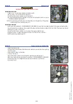
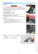
LOADING THE LIFT TRUCK

 -Block the wheels of the platform.

 -Attach the loading ramps to the platform in such a way as to give the shallowest 

possible ramp angle for the lift truck.

 -Load the lift truck parallel to the platform.

 -Stop the lift truck (

e

 1 - OPERATING AND SAFETY INSTRUCTIONS: DRIVING 

INSTRUCTIONS UNLADEN AND LADEN).

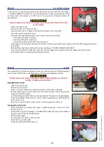
STOWING THE LIFT TRUCK

 -Fix the chocks to the platform at the front and at the back of each tyre.

 -Also fix the chocks to the platform on the inside of each tyre.

 -Secure the lift truck to the platform with sufficiently strong ropes to the anchoring 

points 1 provided.

 -Tighten the ropes.

647732 

(31/10/2019) 

MT 

625 

75K 

ST5 

S1 

/ MT 

625 

75K 

COMFORT 

ST5 

S1

Summary of Contents for MT 625 H 75K COMFORT ST5 S1

Page 1: ...OPERATOR S MANUAL ORIGINAL INSTRUCTIONS US 31 10 2019 647732 MT 625 H 75K ST5 S1 MT 625 H 75K COMFORT ST5 S1...

Page 2: ...ference Hand this manual to the new owner if the lift truck is resold CALIFORNIAPROPOSITION65WARNINGS WARNING This product can expose you to lead which is known to the State of California to cause can...

Page 3: ...views commentaries and instructions even the document organization that are found in this document are the intellectual property of MANITOU BF Any violation of the aforementioned may lead to civil an...

Page 4: ...1 OPERATINGANDSAFETYINSTRUCTIONS 2 DESCRIPTION 3 MAINTENANCE 4 OPTIONALADAPTABLEATTACHMENTSFORTHERANGE 647732 31 10 2019 MT 625 H 75K ST5 S1 MT 625 H 75K COMFORT ST5 S1...

Page 5: ...1 1 1 OPERATING AND SAFETY INSTRUCTIONS 647732 31 10 2019 MT 625 H 75K ST5 S1 MT 625 H 75K COMFORT ST5 S1...

Page 6: ...1 2 647732 31 10 2019 MT 625 H 75K ST5 S1 MT 625 H 75K COMFORT ST5 S1...

Page 7: ...1 3 647732 31 10 2019 MT 625 H 75K ST5 S1 MT 625 H 75K COMFORT ST5 S1...

Page 8: ...NGTHE LIFTTRUCK 1 14 G STOPPINGTHE LIFTTRUCK 1 15 H DRIVINGTHE LIFTTRUCK ONTHE PUBLIC HIGHWAY 1 16 INSTRUCTIONS FOR HANDLING A LOAD 1 18 A CHOICE OF ATTACHMENTS 1 18 B WEIGHT OF LOAD AND CENTRE OF GRA...

Page 9: ...THE LIFTTRUCK 1 31 IFTHELIFTTRUCKISNOTTOBEUSEDFORALONGTIME 1 32 INTRODUCTION 1 32 PREPARINGTHE LIFTTRUCK 1 32 DEF Diesel Exhaust Fluid TANK 1 32 PROTECTINGTHE ENGINE 1 32 PROTECTINGTHE LIFTTRUCK 1 32...

Page 10: ...o be used within a temperature range of 18 C to 43 C In addition to standard equipment mounted on your lift truck many options are available such as road lighting brake lights rotating beacon light re...

Page 11: ...l type trucks MLT range that are non EC type approved tractors point 6 2 of Article R311 1 of the French Highway Code The truck must be fitted with anoperatinglicenceplate Agricultural type trucks MLT...

Page 12: ...l consult your dealer and in the necessary safety conditions to preserve the health of the operator and any third party tIMPORTANT t Yourlifttruckmustbeinspectedperiodicallytoensurethatitremainsincomp...

Page 13: ...1 9 647732 31 10 2019 MT 625 H 75K ST5 S1 MT 625 H 75K COMFORT ST5 S1...

Page 14: ...or if his lift truck is not in good working order or does not comply with the safety notice The operator is prohibited from carrying out any repairs or adjustments himself unless he has been trained f...

Page 15: ...hments to lift people is either forbidden or authorised exceptionally and under certain conditions eregulations in force in the country in which the lift truck is used The pictogram posted at the oper...

Page 16: ...equirements and adopt the correct position in the driver s cab tIMPORTANT t Undernocircumstancesmusttheseatbeadjustedwhilethelifttruckismoving The operator must always be in his normal position in the...

Page 17: ...ktooclosetopowercables Intheeventofhighwinds donotcarryouthandlingworkthatjeopardisesthestabilityofthelifttruckanditsload particularlyiftheloadcatchesthewindbadly Prevent fire risks associated with us...

Page 18: ...Riskofloosinglateralandfrontalstabilityofthelifttruck Theoperatormustremainincontrolofthelifttruck Intheeventofthelifttruckoverturning donottrytoleavethecabinduringtheincident YOURBESTPROTECTIONISTOST...

Page 19: ...IFT TRUCK SAFETY INSTRUCTIONS Never leave the ignition key in the lift truck during the operator s absence When the lift truck is stationary or if the operator has to leave his cab even for a moment p...

Page 20: ...n the central position i e the transverse axis of the axles parallel to the frame depending onthelifttruckmodel Fully raise the stabilisers and turn the shoes inwards dependingonthemodeloflifttruck tI...

Page 21: ...1 17 647732 31 10 2019 MT 625 H 75K ST5 S1 MT 625 H 75K COMFORT ST5 S1...

Page 22: ...of gravity The longitudinal position of the centre of gravity in relation to the heel of the forks Fig B1 is defined on the load chart concerning your lift truck e2 DESCRIPTION DIMENSIONS AND LOAD CH...

Page 23: ...ON COMMAND AND CONTROL INSTRUMENTS In this position the two front wheels must be off the ground E PICKING UP A LOAD ON THE GROUND Approach the lift truck perpendicular to the load with the boom retrac...

Page 24: ...om length Bring the forks to the stop in front of the load by alternately extending and lowering the boom 1 or if necessary moving the lift truck forward 2 fig F2 Apply the parking brake and place the...

Page 25: ...DICATOR If necessary move the lift truck 3 forward fig F7 driving very slowly and carefully Place the load in a horizontal position and put it down on the pile by lowering and retracting the boom 1 2...

Page 26: ...AND LADEN tIMPORTANT t Thisoperationmustbeexceptionalandperformedwithgreatcare Raise the boom and retract the telescopes completely Bring the lift truck into position in front of the elevation fig G2...

Page 27: ...NDICATOR If it is overloaded put the load back down in the place from which it was picked up If possible lower the load without moving the lift truck Raise the boom 1 to release the load retract 2 and...

Page 28: ...ls bumps and potholes or soft ground Ensure that the wind speed is not higher than 36 km h The lift truck must not travel at more than 0 4 m s 1 5 km h i e one quarter walking speed Drive and stop the...

Page 29: ...gproductandensureitsstability lossofproductunderbraking LOADING A TRAILER Approach the side of the trailer in the transport position fig A3 Raise and extend the boom 1 2 until the bucket is above the...

Page 30: ...is prohibited to have arms or legs or generally any part of the body protruding from the basket Ensure that any materials loaded onto the platform pipes cables containers etc cannot fall out Do not p...

Page 31: ...ters moderatewaves takinglongerform 6 Strongbreeze 22 27 39 49 10 8 13 8 Largebranchesinmotion whistlingheardin overheadwires umbrellausebecomesdifficult Largerwavesforming whitecapseverywhere somespr...

Page 32: ...user must ensure that the instruction manual is accessible at all times and that operators have read and understood it INSTRUCTIONS Take up position in a stable place with no risk of slipping Before u...

Page 33: ...1 29 647732 31 10 2019 MT 625 H 75K ST5 S1 MT 625 H 75K COMFORT ST5 S1...

Page 34: ...wedge 1 on the rod of the lifting cylinder and secure with the rod 2 and the pin 3 Slowly lower the boom then stop the hydraulic movements before it comes into contact with the wedge REMOVING THE WEDG...

Page 35: ...battery Disconnect the battery before working on the electrical circuit WELDING Disconnect the battery before any welding operations on the lift truck When carrying out electric welding work on the l...

Page 36: ...Diesel Exhaust Fluid up to the bottom of the filler neck Start up the lift truck to pressurise the circuit and bring it up to working temperature then shut down the engine If necessary top up the tan...

Page 37: ...ependingonthemodeloflifttruck Top up slowly fill the tank with new DEF Diesel Exhaust Fluid up to the bottom of the filler neck dependingonthemodel oflifttruck Refit the drive belts and adjust the ten...

Page 38: ...TION By entrusting the maintenance of your lift truck to the MANITOU network the risk of pollution is limited and the contribution to environmental protection contribution is made WORN OR DAMAGED PART...

Page 39: ...2 1 2 DESCRIPTION 647732 31 10 2019 MT 625 H 75K ST5 S1 MT 625 H 75K COMFORT ST5 S1...

Page 40: ...2 2 647732 31 10 2019 MT 625 H 75K ST5 S1 MT 625 H 75K COMFORT ST5 S1...

Page 41: ...IFICATIONOFTHELIFTTRUCK 2 8 CHARACTERISTICS 2 10 TYRES 2 12 DIMENSIONSANDLOADCHARTS 2 14 VISIBILITY 2 16 INSTRUMENTSANDCONTROLS 2 18 TOWINGDEVICE 2 40 DESCRIPTIONANDUSEOFTHEOPTIONS 2 42 647732 31 10 2...

Page 42: ...OVE INSTRUCTION CAN CAUSE SERIOUS INJURY TOTHE OPERATOR OR OTHER PERSONS N 52563320 3 4 SAFETYPLATESANDSTICKERS tIMPORTANT t Cleanallstickersandsafetyplatessothattheyarelegible Anysafetyplatesandstick...

Page 43: ...MINI 35 C 31 F 4 5 GAZ R134A N 234797 259398 FUEL WATER SEPARATOR FUEL 3 1 52589959 110 120V 10 A N 244130 6 STICKERSANDPLATESUNDERTHEENGINEHOOD REF PARTNO DESCRIPTION 1 244130 Preheatrod OPTION 2 525...

Page 44: ...2 52515381 Mainfunctions 13 265284 Liftingringoncarriage OPTION 14 184276 Steeringselection 15 52580160 Towingforbidden 16 239594 Soundpowerlevel 17 52580168 Cabcompliance 19 52521685 Dieselexhaustpar...

Page 45: ...FOLLOW ANY OFTHE ABOVE INSTRUCTIONS CAN CAUSE SERIOUS INJURY TOTHE OPERATOR OR OTHER PERSONS 1 Lower boom to the ground 2 Place controls in neutral 3 Apply parking brake 4 Stop engine WHEN PARKING OR...

Page 46: ...er parts or when you require any technical information always specify NOTE For the owner s convenience it is recommended that a note of these numbers is made in the spaces provided at the time of the...

Page 47: ...redegravit Centreofgravity Capacit Nominale Ratedcapacity Pressionservice Workingpressure REARAXLE Type Serialnumber MANITOUpartNo CAB Constructeur Manufacturer TypeCabine Cabintype Num rodes rie Seri...

Page 48: ...ctional MAX MIN displacement cu in r cm3 tr 1 77 6 71 29 110 Transfer gear box DANA Front axle DANA Differential 45 limitedslipdifferential Rear axle DANA Differential Withoutlocking Drive wheels Perm...

Page 49: ...94 32 9 Tilting movements Unladen digging s s 3 5 36 7 Unladen discharging s s 3 6 35 6 SPECIFICATIONS AND WEIGHTS Speed of movement for lift truck in standard configuration on flat ground Front unlad...

Page 50: ...6 81 2 350 772 5 00 71 12 2 50 35 56 70 10 85 140 21 70 1100 2425 7 01 99 71 3 50 49 78 157 24 34 314 48 67 1250 2756 7 02 99 85 3 50 49 78 178 27 59 357 55 34 3250 7165 11 02 156 74 5 51 78 37 295 4...

Page 51: ...2 13 647732 31 10 2019 MT 625 H 75K ST5 S1 MT 625 H 75K COMFORT ST5 S1...

Page 52: ...mm H H1 I in mm 23 74 603 J in mm 31 38 797 K ft in mm 3 4 1015 L in mm 1 77 45 N ft in mm 4 3 7 1314 O in mm 4 92 125 P2 37 37 P3 52 52 R ft in mm 10 4 3150 S ft in mm 21 9 9 6651 5 T ft in mm 12 10...

Page 53: ...2000Lb 2640Lb 4400Lb 3300Lb Feet Meters 11ft0in 9ft4in 8ft4in 6ft11in 5ft3in 4ft3in 0 Meters 1 2 3 4 19ft1in 15 0 1 2 3 4 5 6 7 13 10 5 23 20 10 5 0 0 Feet 3ft7in 68 2 60 50 0 40 30 20 10 24in D C B A...

Page 54: ...ONANDADJUSTMENTOFREAR VIEWMIRRORS 1 LEFT REAR VIEW MIRROR 2 MAIN RIGHT REAR VIEW MIRROR 3 CENTRAL RIGHT REAR VIEW MIRROR 4 UPPER RIGHT REAR VIEW MIRROR 5 INSIDE REAR VIEW MIRROR OPTION 6 REAR VIEW MIR...

Page 55: ...2 17 647732 31 10 2019 MT 625 H 75K ST5 S1 MT 625 H 75K COMFORT ST5 S1...

Page 56: ...ANDTRANSMISSION CUT OFF 2 34 20 FORWARD NEUTRAL REVERSE GEAR SELECTION 2 34 21 STEERING SELECTION 2 35 22 HEATER CONTROL 2 36 23 AIR CONDITIONING CONTROLS AIR CONDITIONING OPTION 2 36 24 HEATINGVENTS...

Page 57: ...12 36 6 7 37 38 29 30 13 32 31 MT625HCOMFORT75KST5 29 30 13 32 MT625H75KST5 26 39 3 4 9 14 8 17 19 18 25 5 15 20 25 27 28 33 16 9 22 21 24 25 10 2 23 647732 31 10 2019 MT 625 H 75K ST5 S1 MT 625 H 75...

Page 58: ...sediftheseatbeltisdefective fixing locking cuts tears etc Immediatelyrepairorreplacethesafetybelt Sit correctly on the seat Check that seat belt is not twisted Place the seat belt at hip level Attach...

Page 59: ...t will not shift into another position tIMPORTANT t Onlyoperatetheleverbyitsrecessedsectionanddonotgraspfrombelow attheriskofcrushingthehand LUMBAR ADJUSTMENT This increases the comfort of the seat an...

Page 60: ...mple tIMPORTANT t Operatethebatterycut offforaminimumof30secondsafterhavingswitchedofftheignitionwiththeignitionkey 7 BATTERY 5 EMERGENCYSTOP In the event of danger it enables the engine to be shut do...

Page 61: ...l speed 9 LEDs Red zone 230 F 239 F or 110 C 115 C 10 LEDs Red zone 239 F or 115 C Stop the lift truck seek the cause of overheating NOTE If the red indicator lamp and the buzzer come on 230 F or 110...

Page 62: ...uck is running to indicate that the automatic exhaust purification is disabled e SWITCHES HIGH EXHAUST GAS TEMPERATURE INDICATOR LAMP The indicator lamp comes on while the lift truck is operating to i...

Page 63: ...RE FILTER WARNING INDICATOR LAMP This light will come on when there is water in the fuel pre filter Stop the lift truck and carry out the necessary repairs NOT USED INDICATOR LIGHTS INDICATOR LAMP FRO...

Page 64: ...the time remaining before maintenance In the event that the deadline is exceeded the hours are shown with a plus sign Press once more on the button to return to the hour meter screen The maintenance k...

Page 65: ...lights up and an audible signal confirms deactivation To reactivate the automatic exhaust purification hold down the bottom of the switch again The indicator lamp goes out to confirm reactivation EXH...

Page 66: ...AND USE OF THE OPTIONS ATTACHMENT HYDRAULIC CONTROL FORCED OPERATION OPTION MT625HCOMFORT75KST5 e DESCRIPTION AND USE OF THE OPTIONS BOOM ELECTRICAL PREDISPOSITION OPTION MT625HCOMFORT75KST5 e DESCRIP...

Page 67: ...OPTION F6 10A Presence of driver on seat Retraction and boom angle sensors F7 10A Hydraulics electronic control unit F8 5A Deactivation of aggravating hydraulic movement cut off 7 5A Deactivation of...

Page 68: ...ke lights K4 Free Working lights on boom OPTION K5 Air conditioning electric fan OPTION K6 Air conditioning compressor OPTION K7 Heating K8 Flashing unit K9 Not used Free K10 Air conditioning OPTION I...

Page 69: ...tch sounds the horn NOTE Positions D E F G can be used without switching on the ignition 15 FRONTANDREARWINDSCREENWIPERSWITCH FRONT WINDSCREEN WIPER A Front windscreen wiper stop B Front windscreen wi...

Page 70: ...ifting tilting telescoping and attachment controls a safety device is added to the lift truck SECONDFIT FIRSTFIT NO HYDRAULIC CONTROLS ACTIVATION Placeyourhandontheleverandperformthehydraulicmovement...

Page 71: ...esired flow and confirm with the button The screen appears on the lower screen display Turn button C backwards to select a hydraulic flow for circuit A between 10 and 100 Hold button C at the desired...

Page 72: ...ator must observe the following sequence of operations to move the truck forwards or backwards 1 sit down correctly in the driver s seat 2 release the parking brake 3 engage forward or reverse To stop...

Page 73: ...rcle B3 Front and rear drive wheels in the same direction crabwise movement CHECKING WHEEL ALIGNMENT tIMPORTANT t Beforetravellingonapublicroad itisnecessarytochecktherearwheelalignmentandtotravelonfr...

Page 74: ...sthecompressorisliabletobedamagedbycoolantintheliquidstate Ifyourairconditioningdoesnotseemtobeworkingcorrectly haveitexaminedbyyourdealer Nevertrytorepairanyfaultsyourself A FAN CONTROL This 3 speed...

Page 75: ...OPENING EMERGENCY EXIT Use the rear window as an emergency exit if it is impossible to leave the cab by the door 31 REARSTORAGESPACE MT625HCOMFORT75KST5 32 DOCUMENTSTORAGENET Make sure that the operat...

Page 76: ...cator light B Left rear brake light C Left rear light D Rear fog light E Reversing light F Right rear light G Right rear brake light H Right rear indicator light 36 ROTATINGBEACONLIGHT DEPENDINGONASSE...

Page 77: ...rapproachwithaflameduringfillingoperationsorwhenthetankisopen Neverrefillwhileengineisrunning If necessary add diesel e 3 MAINTENANCE LUBRICANTS AND FUEL Remove cap 1 Fill the fuel tank with clean die...

Page 78: ...icle weight AGVW tractive effort and maximum vertical force on the coupling point This information is given on the manufacturer s plate fixed to each lift truck e IDENTIFICATION OF THE LIFT TRUCK To u...

Page 79: ...the female socket 1 on the lift truck and make sure the lights of the trailer or the light bar are working properly 3 COUPLINGFITTING OPTION tIMPORTANT t Becarefulnottogetyourfingerscaughtorcrusheddu...

Page 80: ...s switched off and the engine is stopped 2 MODCODANTI THEFTSYSTEM OPERATION Switch on lift truck ignition red LED 1 will flash Enter your user code followed by V to validate green LED 2 will light Sta...

Page 81: ...You can restart the lift truck within 20 seconds of stopping it after this time the anti start system reacts and red LED 1 flashes 6 EXTERIORDRAIN BACK Enables connection of an attachment for which dr...

Page 82: ...preventaccidentalunlockingofthe attachment HYDRAULIC ATTACHMENT CONTROL Put the tap in position B and press switch 2 at position B indicator lamp on Push switch 3 forward or backward 7 WATERPROOFDOCUM...

Page 83: ...on and hold down button 3 Push switch 2 forward or backward 11 BOOMHEADELECTROVALVE HYDRAULICATTACHMENTLOCKING MT625HCOMFORT75KST5 Enables the use of a hydraulic function and hydraulic locking of the...

Page 84: ...ust be restarted 13 ENGINESPEEDREGULATOR MT625HCOMFORT75KST5 tIMPORTANT t Thisoptioncannotunderanycircumstancesbeusedwhiledrivingontheroad Cautionwhendriving suddenaccelerationorbrakingwhenyouusebutto...

Page 85: ...ted angle which is 45 Do not change the angle of the carriage while using the lifting ring The lifting hook the chains and slings shall have a minimum capacity of 6614 lbs 3000 kg with a safety coeffi...

Page 86: ...2 48 647732 31 10 2019 MT 625 H 75K ST5 S1 MT 625 H 75K COMFORT ST5 S1...

Page 87: ...3 1 3 MAINTENANCE 647732 31 10 2019 MT 625 H 75K ST5 S1 MT 625 H 75K COMFORT ST5 S1...

Page 88: ...SANDFUEL 3 10 10H DAILYSERVICEOREVERY10HOURSOFSERVICE 3 12 50H WEEKLYSERVICEOREVERY50HOURSOFSERVICE 3 14 500H PERIODICSERVICE EVERY500HOURSOFSERVICEOR1YEAR 3 20 1000H PERIODICSERVICE EVERY1000HOURSOFS...

Page 89: ...TIONS YOUBENEFITFROMOURKNOW HOW Through its network MANITOU provides the user with Know how and competence The guarantee of high quality work Original replacement parts Help with preventive maintenanc...

Page 90: ...he lift truck DAILYANDWEEKLYMAINTENANCE 10H DAILYSERVICEOREVERY10HOURSOFSERVICE CHECK Lift truck environment 3 12 CHECK Engine oil level 3 12 CHECK Cooling liquid level 3 12 CLEAN Cyclonic pre filter...

Page 91: ...K Hydraulic oil level 3 16 CHECK Windscreen washer liquid level 3 16 CLEAN Fuel pre filter 3 16 CLEAN Radiator cores 3 17 CLEAN Dry air filter cartridge 3 17 CLEAN Condenser wiring harness Air conditi...

Page 92: ...OUNTER DATEOFSERVICING 500H PERIODICSERVICE EVERY500HOURSOFSERVICEOR1YEAR CHECK Hydraulic oil 3 20 REPLACE Engine oil 3 20 REPLACE Engine oil filter 3 20 REPLACE Fuel filter 3 21 REPLACE Fuel pre filt...

Page 93: ...LACE Intake hose 3 29 REPLACE Pressure detection hoses for the oversupply sensor 3 29 REPLACE Exhaust gas recirculation cooler hoses EGR 3 29 REPLACE Water hose 3 29 REPLACE Lubrication hose 3 29 REPL...

Page 94: ...ion system EGR 3 33 CLEAN Exhaust particle filter DPF 3 33 Engineservice consultyourdealer OCCASIONALMAINTENANCE CLEAN Stationary lift truck exhaust purification 3 34 REPLACE Wheels 3 35 REPLACE Batte...

Page 95: ...EAFTER500HOURSOFSERVICE ALTERNATOR BELT Part number 749473 DRY AIR FILTER CARTRIDGE Part number 563416 ENGINE CRANKCASE VENTILATION FILTER Part number 940867 2000H PERIODICSERVICE EVERY2000HOURSOFSERV...

Page 96: ...C 40 C 50 C COOLING CIRCUIT 12 7USqt 12 COOLANT 35 C 40 F 22 F 4 F 14 F 32 F 50 F 68 F 86 F 104 F 122 F 40 C 30 C 20 C 10 C 0 C 10 C 20 C 30 C 40 C 50 C FUEL TANK 16 6USgal 63 GNRHPDIESELFUEL BOOM DE...

Page 97: ...REAR AXLE OSCILLATION MANITOUBLUEMULTI PURPOSELUBRICANT 40 F 22 F 4 F 14 F 32 F 50 F 68 F 86 F 104 F 122 F 40 C 30 C 20 C 10 C 0 C 10 C 20 C 30 C 40 C 50 C REAR WHEEL REDUCING GEAR PIVOTS MANITOUBLACK...

Page 98: ...engine housing and the central part of the frame is necessary to see how frequently it needs to be cleaned to prevent these potential accumulations of material or leakages CHECK Engineoillevel Place...

Page 99: ...nd cleaned as soon as impurities reach the MAX level on the tank tIMPORTANT t Whencleaning takecarenottoletimpuritiesintothedryairfilter Loosen nut 1 remove cover 2 and empty the tank Clean the pre fi...

Page 100: ...RIPTION TYRES NOTE There is an OPTIONAL wheel tool kit CHECK Transferboxoillevel Place the lift truck on level ground with the engine stopped Visually check for any traces of seepage or leakage from t...

Page 101: ...bs 34 49 N m CHECK Brakefluidlevel Place the lift truck on level ground tIMPORTANT t Ifthebrakeoillevelisabnormalconsultyourdealer Open the protective casing 1 with the ignition key Check tank 2 The c...

Page 102: ...e under the drain plug 2 and unscrew it by two thread turns Allow the diesel fuel to flow out until it is free from impurities and water Re tighten drain plug 2 and reconnect the wiring harness 1 CHEC...

Page 103: ...ning is completed when there is no more dust on the cartridge Clean the cartridge seal surface with a damp clean lint free cloth and grease with a silicone lubricant MANITOU part No 479292 Check visua...

Page 104: ...of the carriage pin 1 lubricator 3 Lubricator of the tilting cylinder foot pin 1 lubricator 4 Lubricator of the tilting cylinder head pin 1 lubricator 5 Lubricator of the lifting cylinder foot pin 1 l...

Page 105: ...w and discard the engine oil filter 4 together with its seal Clean the filter bracket with a clean lint free cloth Lightly oil the seal before refitting the new oil filter e FILTER ELEMENTS AND BELTS...

Page 106: ...ngine tIMPORTANT t Disposeofthedrainoilinanecologicalmanner Tightentheoilfilterbyhandpressureonlyandlockthefilterinplacebyaquarterturn DRAINING THE OIL Open the engine cover Remove access panel 1 NOTE...

Page 107: ...r lubricated with clean diesel beforehand e FILTER ELEMENTS AND BELTS Reconnect the wiring harness 1 Open bleed screws 3 and 4 Turn on the lift truck s ignition with the ignition key Close the bleed s...

Page 108: ...ridge 4 with a twisting motion Refit the head onto a new cartridge e FILTER ELEMENTS AND BELTS Fit the assembly in place and re tighten cover 2 Put the cap 1 back REPLACE Frontaxledifferentialoil Plac...

Page 109: ...he protective grid 1 Remove the cab ventilation filter and replace it with a new one eFILTER ELEMENTS AND BELTS Refit the protective grid REPLACE Hydraulicfluidtankfiltercap Place the lift truck on le...

Page 110: ...ap is given a sharp tug NOTE After an accident replace the seat belt CLEAN Fueltank Place the lift truck on level ground with the engine stopped tIMPORTANT t Whilecarryingouttheseoperations donotsmoke...

Page 111: ...the belt tension between the crankshaft pulley and the alternator pulley 22 03 lbs 98 N The clearance should be about 0 3 to 0 4 in 7 to 9 mm Swivel the alternator assembly so as to obtain the require...

Page 112: ...engine at idle for a few minutes Check for any possible leaks Check the level and refill if necessary REPLACE Dryairfiltercartridge In case of use in a heavily dust laden atmosphere there are pre fil...

Page 113: ...itandtightenthelevelandfillingplug2 tighteningtorque25 36ft lbs34 49N m REPLACE Frontwheelreduceroil REPLACE Rearwheelreduceroil Place the lift truck on level ground with the engine stopped and the re...

Page 114: ...CK Brakesystempressure CHECK Boompadwear CHECK Conditionofwiringharnessesandcables CHECK Lightsandsignals CHECK Warningindicators CHECK Conditionoftherear viewmirrors CHECK Cabinstructure CHECK Frames...

Page 115: ...eoversupplysensor REPLACE Exhaustgasrecirculationcoolerhoses EGR REPLACE Waterhose REPLACE Lubricationhose REPLACE Radiatorhosesandclampingcollars REPLACE Fuelhosesandclampingcollars REPLACE Brakeflui...

Page 116: ...dgereplacementfrequencyisgivenforinformationonly Itmustbechangedeverysecondtimethe dryairfiltercartridgeischanged For the dismantling and refitting of the cartridge e 1000 HOURS REPLACE Air filter car...

Page 117: ...under drain plugs 1 and unscrew them Remove the filler plug 2 to ensure correct drainage REPLACING THE BRAKE ACCUMULATOR UNIT FILTER Remove the cover plate 3 Unscrew plug 4 remove and replace the fil...

Page 118: ...RYTECHNICALKNOWLEDGEANDTOOLS Inanyofthefollowingcircumstances calladoctor Ifinhaled takethevictimtofreshair Ifthereiscontactwiththeskin washimmediatelywithplentyofwater Ifthereisfrostbite applyasteril...

Page 119: ...ARS ALSOPERFORMTHE500HOURAND1000HOURPERIODICMAINTENANCEOPERATIONS CHECK Turbocharger CHECK Exhaustgasrecirculationsystem EGR CLEAN Exhaustparticlefilter DPF Engineservice consultyourdealer 647732 31 1...

Page 120: ...this event check the positioning of the lift truck and contact your dealer if necessary At the end of the procedure indicator lamps go out During the procedure the engine speed increases to approx 180...

Page 121: ...be changed Unlock the nuts of the wheel to be changed Place the jack under the flared axle tube as near as possible to the wheel and adjust the jack Raise the wheel until it is clear of the ground and...

Page 122: ...itchedofftheignitionwiththeignitionkey Handlingandservicingabatterycanbedangerous takethefollowingprecautions Wearprotectivegoggles Keepthebatteryhorizontal Neversmokeorworknearanakedflame Workinawell...

Page 123: ...3 37 647732 31 10 2019 MT 625 H 75K ST5 S1 MT 625 H 75K COMFORT ST5 S1...

Page 124: ...by no more than three turns RELEASING THE PARKING BRAKE ON THE FRONT AXLE Unscrew the screws 2 on the front axle remove the shims 3 and fully re tighten the screws 2 TOWING Switch on the hazard warnin...

Page 125: ...boshaft withoutlubricationwhentransportingthevehicle LOADING THE LIFT TRUCK Block the wheels of the platform Attach the loading ramps to the platform in such a way as to give the shallowest possible r...

Page 126: ...3 40 647732 31 10 2019 MT 625 H 75K ST5 S1 MT 625 H 75K COMFORT ST5 S1...

Page 127: ...4 OPTIONAL ADAPTABLE ATTACHMENTS FOR THE RANGE 4 1 647732 31 10 2019 MT 625 H 75K ST5 S1 MT 625 H 75K COMFORT ST5 S1...

Page 128: ...4 2 647732 31 10 2019 MT 625 H 75K ST5 S1 MT 625 H 75K COMFORT ST5 S1...

Page 129: ...smassandcentreofgravity Shouldtheattachmenthavealowercapacitythanthelifttruck neverexceedthislimit Some particular uses require the adaptation of the attachment which is not provided in the price list...

Page 130: ...under the locking tube of the attachment slightly raise the boom tilt the carriage backwards in order to position the attachment Fig C Lift the attachment off the ground to facilitate locking MANUAL...

Page 131: ...therapidconnectorsarecleanandprotecttheholeswhicharenotused withthecapsprovided Take the locking pin on the bracket and lock the attachment fig D Do not forget to fit the cotter pin Stop the engine an...

Page 132: ...g STANDARDISED SIDE SHIFT CARRIAGE TDL2T5L1020FEM2 TDL2T5L1260FEM2 PARTNO 751370 751371 Rated capacity 2300kg 2300kg Side shift 2x100mm 2x100mm Width 1020mm 1260mm Ground 54kg 67kg STANDARDISED FORK P...

Page 133: ...ARRIAGE TFF29MT 1040 PARTNO 653340 Rated capacity 2900kg Width 1040mm Ground 285kg FLOATING FORK PARTNO 211919 Section 125x40x1200mm Ground 62kg 4 7 647732 31 10 2019 MT 625 H 75K ST5 S1 MT 625 H 75K...

Page 134: ...Ground 320kg LOADING BUCKET CBR730L1850 PARTNO 571831 Rated capacity 735l Width 1850mm Ground 330kg MULTIPURPOSE BUCKET DISPLAY CB4X1 700L1950 PARTNO 751402 Rated capacity 700l Width 1950mm Ground 64...

Page 135: ...ITH SPOUT ADAPTABLE ON FORKS BBHG500S4 PARTNO 751464 Rated capacity 500l 1300kg Width 1100mm Ground 235kg SPOUT BUCKET ADAPTABLE ON FORKS GL600S2 PARTNO 174373 Rated capacity 600l 1440kg Ground 290kg...

Page 136: ...essthanorequaltothewidthofthebucket PARTNO 206734 206732 206730 Width 1375mm 1500mm 1650mm PARTNO 235854 206728 206726 Width 1850mm 1950mm 2000mm PARTNO 223771 223773 206724 Width 2050mm 2100mm 2150mm...

Reviews: