4-5
O w n e r ’ s M a n u a l
Connections
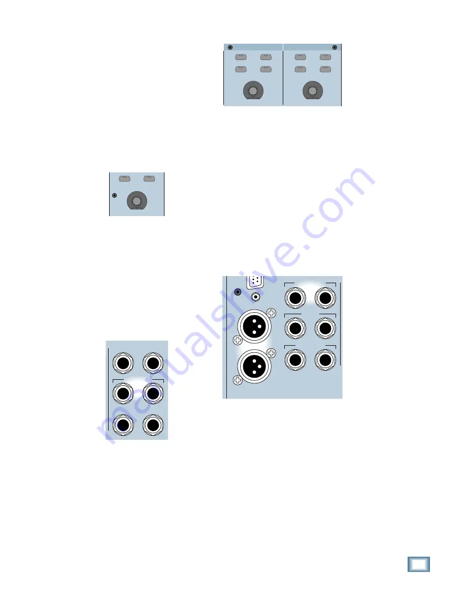
Many engineers and producers like to listen
to their mix on standard reference monitors as
well as on smaller monitors. Typically, you use
the MAIN output for your standard reference
monitors, and the NEAR FIELD output for
smaller or alternative monitor listening.
You can select the signal source sent to the
control room outputs in the Control Room
Section. Though both outputs carry the same
signal, only one output can be switched on at a
time. Use the MAIN and NEAR FIELD buttons
in the Control Room Section to quickly switch
back and forth between them. Use the
SPEAKER LEVEL V-Pot to adjust their
individual output levels.
NEAR FIELD
MAIN
SPEAKER LEVEL
SPEAKERS
Connecting Studio Monitors
One pair of 1/4" TRS stereo line-level outputs
is provided on the rear panel for sending signals
to the studio (or wherever you want it to go).
Connect these outputs to a power amplifier and
speakers, or powered monitor speakers, or a
headphone distribution amplifier (DA) for the
musicians. This is the same signal that is
assigned to the Control Room outputs. However,
it is not affected by the DIM button in the
Control Room Section, nor is it interrupted when
a channel is soloed.
TALKBACK
PHONES 2
PUNCH I/O
PHONES 1
STUDIO OUT
L R
Connecting Headphones
There are two 1/4" TRS headphone output
jacks labeled PHONES 1 and PHONES 2. They
are located just above the STUDIO OUTS on
the rear panel of the Digital 8•Bus. You can
independently assign the signal going to these
two outputs and adjust their output levels in
the Phones/Cue Mix Section.
CONTROL ROOM
COPY MIX TO CUE
AUX 9-10
AUX 11-12
CONTROL ROOM
COPY MIX TO CUE
AUX 9-10
AUX 11-12
LEVEL
LEVEL
PHONES/CUE MIX 1
PHONES/CUE MIX 2
These outputs are designed for stereo
headphones, where the tip and ring carry the
left and right channel signals respectively, and
the sleeve is the ground return for both signals.
Connecting Your Final Mix Deck
After you’ve finished all your tracking and
you’re ready to make your final mixdown to
2-track, use the 1/4" TRS MASTER OUT or
XLR MASTER OUT jacks on the rear panel to
connect to your 2-track recorder. The same
signal appears at the 1/4" and XLR outputs,
with the exception that the 1/4" jacks have a
maximum output level of +22 dBu, and the
XLR jacks have a maximum output level of
+28 dBu. These can both be connected to
balanced or unbalanced inputs, so choose the
one that matches your 2-track deck.
MASTER OUT
MASTER OUT
L
R
CR
MAIN
CR
NEAR FIELD
L R
L R
L R
If you’re mixing down to DAT, use one of the
digital OUT connectors on the DIGITAL I/O
card, which is equipped with an AES/EBU
XLR-type OUT connector, and a S/PDIF RCA-
type OUT connector. Select the output you
want to use in the Digital I/O Setup menu (I/O
CARDS button in the Setup Section, or Setup/
Digital I/O on the screen).
You’ll probably want to monitor the final mix
from the 2-track tape you’re recording with. To
do this, connect the outputs from your 2-track
deck to one of the 2 TRACK inputs (A, B, or C)
on the rear panel of the Digital 8•Bus. Then
select the corresponding 2 TRACK source in
the Control Room Section.
Summary of Contents for 8-BUS Series
Page 49: ...3 16 D i g i t a l 8 B u s Start Up ...
Page 57: ...4 8 D i g i t a l 8 B u s Connections ...
Page 77: ...5 20 D i g i t a l 8 B u s Preparing for a Session ...
Page 177: ...7 20 D i g i t a l 8 B u s Automation ...
Page 207: ...D 2 D i g i t a l 8 B u s Apogee UV22 ...
Page 219: ...F 4 D i g i t a l 8 B u s Optional I O Cards ...
Page 227: ...H 2 D i g i t a l 8 B u s Upgrading ...
Page 235: ...K 2 D i g i t a l 8 B u s ...
Page 237: ...D i g i t a l 8 B u s ...
Page 239: ...D i g i t a l 8 B u s ...


