6-8
D i g i t a l 8 • B u s
Starting a New Session
Routing Mixer Channels to Tape Outputs and Buses
16 internal Effects Returns, the 8 ALT Returns, and
the BUS OUT 1–8 can be assigned to a tape out.
Note:
You can assign only one channel to a direct
tape output. Similarly, you can’t assign a channel
to more than one tape out.
Adjusting for Nominal Input and Output Levels
Refer to the “Input Sensitivity Adjustment
Procedure” on page 6–1 to properly set the
TRIM controls on channels 1–24.
Now we’ll concentrate on getting the optimum
signal level from the Digital 8•Bus to the recorder.
This is actually a simple procedure from the
Digital 8•Bus’ point of view. The signal going to
tape is pre-fader, so the fader levels won’t affect
the signal going to tape.
The channel V-Pots can be configured as Tape
Send level controls. Just press the LEVEL TO
TAPE button and use the channel V-Pots to
adjust the signal level as it appears in your
recorder’s meter. You should refer to your
recorder’s instruction manual at this point and
review their recommendations on setting input
levels for recording. Generally, you will want to
keep the channel fader close to the “U” designa-
tion, which provides a +4 dBu output from the
Digital 8•Bus to the recorder (if you’ve followed
the Input Sensitivity Adjustment Procedure).
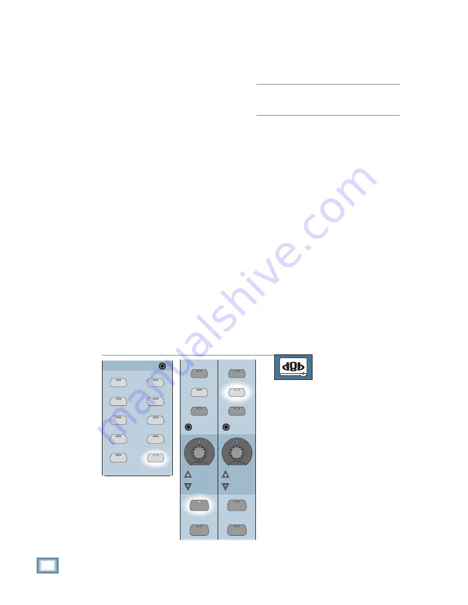
TO ASSIGN CHANNELS TO TAPE OUTPUTS
From the console:
1. Press the ROUTE TO TAPE button in
the Bus Assignment Section.
2. Press the SELECT button on the chan-
nel you want to route to tape. This
could be any of the channels 1–24 on
Bank 1, channels 25–48 on Bank 2,
FX Returns on Bank 3, or BUS 1–8 on
Bank 4.
3. Press the ASSIGN button on the chan-
nel whose TAPE OUT you want to
route to the selected channel. It is not
necessary to change banks when
pressing the ASSIGN button. Since
there are only 24 Tape Outputs (and
24 ASSIGN buttons), the console
knows which Tape Output you are as-
signing the selected channel to.
BUS 1
BUS 2
BUS 3
BUS 4
BUS 5
BUS 7
BUS 6
BUS 8
L-R
ROUTE TO
TAPE
ASSIGNMENT
ASSIGN
ASSIGN
ASSIGN
ASSIGN
ASSIGN
ASSIGN
ASSIGN
ASSIGN
ASSIGN
ASSIGN
13
37
12
36
ASSIGN
WRITE
ASSIGN
WRITE
REC/RDY
REC/RDY
SELECT
SOLO
SELECT
SOLO
If you have only one source going to one tape
track, you’ll simply assign the source to a Tape
Output. If you have to combine two or more in-
puts onto one or two tracks (two trumpets on one
track, five drum mics panned across a pair of
tracks), you must assign the inputs to a common
bus or pair of buses, because you can’t assign
more than one channel to a Tape Out.
Why you’d use a direct tape out:
• You want to have a single voice or instrument
on one track for later mixdown.
• You’ve already assigned all eight of your buses
to other duties.
Why you’d use a bus:
• You want to economize tracks by combining
several microphones onto a single track.
• It’s there, it’s easy, it sounds great.
• You want to help reduce single-occupancy-
vehicles (SOVs) on the road by using the bus.
Assigning Channels to a Tape Output
The tape out assignment defaults to off; that
is, no channels are assigned to the tape outputs.
You can assign a channel to any tape output by
using the ASSIGN button along with the ROUTE
TO TAPE button in the Assignment Section.
There are 24 direct Tape Outputs. Any of the 48
channels can be assigned to a tape out. In addition, the
Summary of Contents for 8-BUS Series
Page 49: ...3 16 D i g i t a l 8 B u s Start Up ...
Page 57: ...4 8 D i g i t a l 8 B u s Connections ...
Page 77: ...5 20 D i g i t a l 8 B u s Preparing for a Session ...
Page 177: ...7 20 D i g i t a l 8 B u s Automation ...
Page 207: ...D 2 D i g i t a l 8 B u s Apogee UV22 ...
Page 219: ...F 4 D i g i t a l 8 B u s Optional I O Cards ...
Page 227: ...H 2 D i g i t a l 8 B u s Upgrading ...
Page 235: ...K 2 D i g i t a l 8 B u s ...
Page 237: ...D i g i t a l 8 B u s ...
Page 239: ...D i g i t a l 8 B u s ...


