Assembly- and Installation
Instructions
Lohberger Heiztechnik
GmbH
N28/HB N28/GB
Seite 35
Lohberger Heiztechnik GmbH, A-5020 Salzburg-Bergheim, Rechtes Salzachufer 40
Tel. 0662-450444-0, Fax-DW 9
Es gelten unsere aktuellen allgemeinen Geschäftsbedingungen. Irrtum, Druckfehler und technische Änderungen vorbehalten
8.9.4
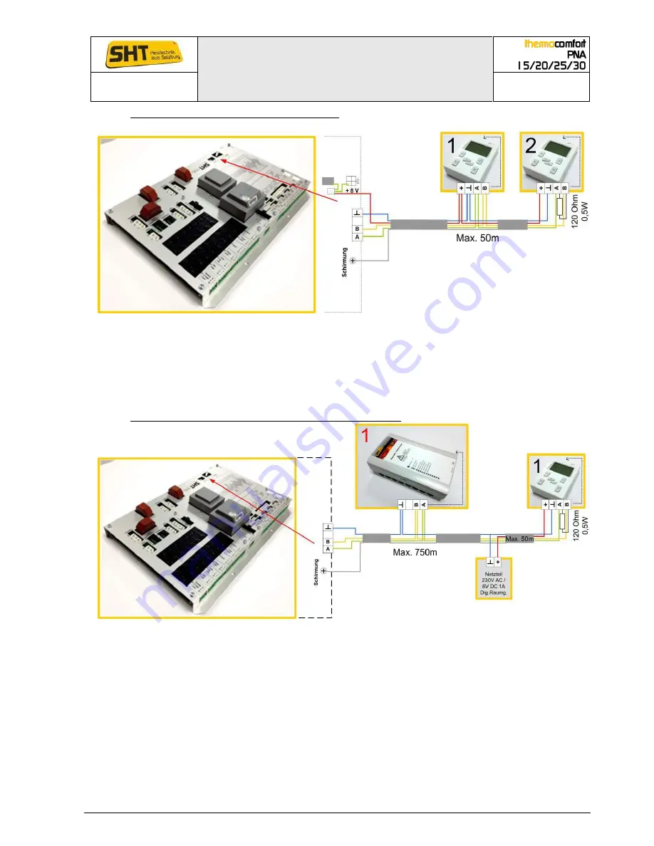
I/O board with digital-room unit 1 and 2:
The unit is fed from the boiler (via the bus cable) (+ conductor dragged along).
Fit the shield only to the I/O board. Loop in the device 1 (do not connect with chassis or
earthing). Bus load resistance 120 Ohm 0,5 Watt clamp to the device 2 between A and B
Maximum cable length is 50m. For longer cable lengths the wire cross section must be bigger,
(see above) or a external mains unit must be fitted (see next diagramm).
8.9.5
I/O board with bus module 1 and digital-room unit 1:
Bus module 1 is fed via a seperate AC power line!
Room unit 1 is fed via an external power supply unit (necessary if the cable length to the boiler is
more than 50m).
Fit the shield only to the I/O board.
Bus load resistance 120 Ohm 0,5 Watt clamp in this sequence to both devices between A and B.


