Assembly- and Installation
Instructions
Lohberger Heiztechnik
GmbH
N28/HB N28/GB
Seite 16
Lohberger Heiztechnik GmbH, A-5020 Salzburg-Bergheim, Rechtes Salzachufer 40
Tel. 0662-450444-0, Fax-DW 9
Es gelten unsere aktuellen allgemeinen Geschäftsbedingungen. Irrtum, Druckfehler und technische Änderungen vorbehalten
6.7
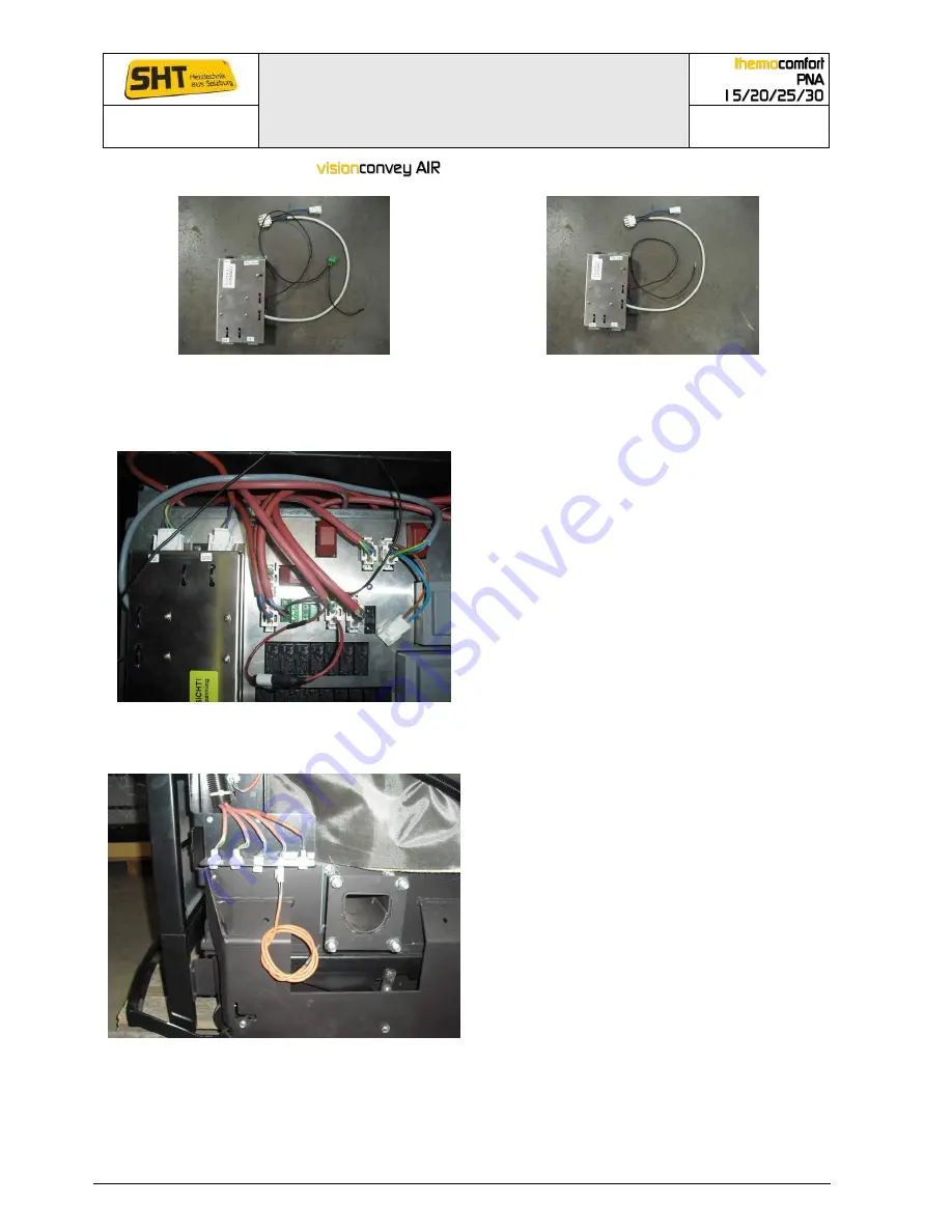
Fitting relay box for
screw conveyor system & cabeling
Relay box at delivery
Relay box suitable for fitting
To be able to use the relay box remove the green 3-pole plug and the short black cable (see
picture on the left) before assembly.
Cable connection relay box with main circuit board
Assemble the relay box to the left of the main
circuit board on the designated bolts. The
fuse and the green plug of the relay box face
to the front.
Connect the gray cable of the relay box to
slot 3 on the main circuit board.
Connect the previously removed cable with
the plug labelling 3 to the relay box X2.
Connect the black cable of the relay box to
the 4-pole green plug (19) in position 3
between N and L.
Connect the loose cable STL-F to the relay
box.
6.8
Assembly cable connection at pellet insertion
Connection relay box with the main circuit board
The electrical connection panel is located on the
bottom right outside of the boiler and is covered
by a lid of the casing from the outside. For
plugging into the power strip open the covering
lid.
Connection feeding motor (2)
Connection discharge motor (3/X2)
Connection feeding sensor (17)
Connection insertion sensor (13)
Connection STL-drop shaft (STL-F)
The recess in the cover is adjacent to the
insertion shaft and is provided to lead the cables.


