Assembly- and Installation
Instructions
Lohberger Heiztechnik
GmbH
N28/HB N28/GB
Seite 14
Lohberger Heiztechnik GmbH, A-5020 Salzburg-Bergheim, Rechtes Salzachufer 40
Tel. 0662-450444-0, Fax-DW 9
Es gelten unsere aktuellen allgemeinen Geschäftsbedingungen. Irrtum, Druckfehler und technische Änderungen vorbehalten
6.5
Assembling Safety Temperature Limiter (STL) & Boiler Probe & Control Board Cable
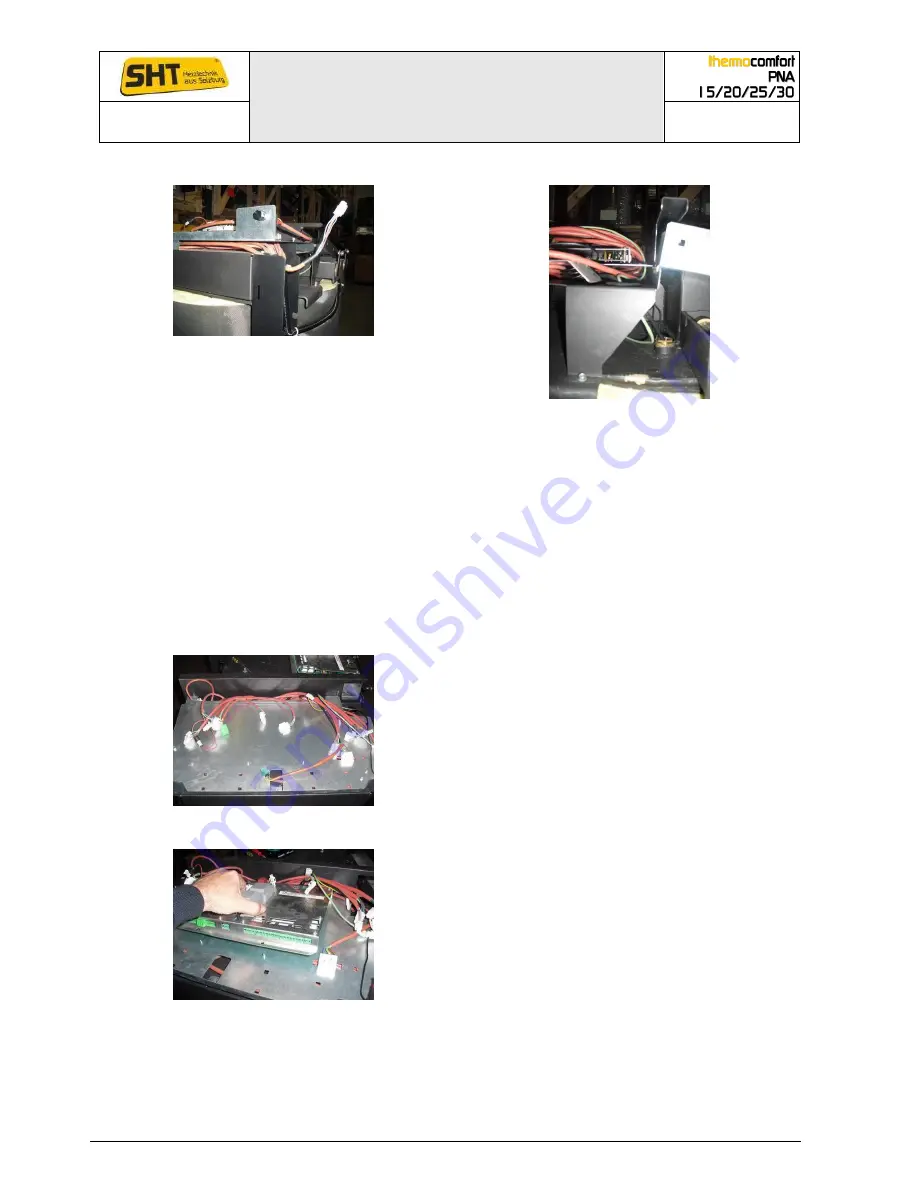
Position STL & control unit cable
Position STL capillary probe & boiler probe
The safety temperature limiter (STL) and the control board cable are located on the front top
right. STL has to be screwed on and the cables are stowed below the circuit board carrier plate
and the plug is passed over the rear cable slot up to the circuit board, the capillary tube is fed to
the thermowell on the right side of the clining lid.
The boiler probe as well as the STL probe are inserted into the same thermowell and led to the
circuit board via the rear cable.
Both probes are secured with a wire retaining spring from slipping out of the thermowell.
The loose end of the control board cable is later connected to the control unit on the casing. The
remaining cable is tucked under the circuit board carrier plate and led out and upwards through
the rear cable slot.
6.6
Assembling I/O-circuit board & cable connection
Position I/O-circuit board carrier plate
The circuit board carrier plate is on the top front
of the boiler. All internal cables lead to the top
through the rear cable slot.
Insertion of the I/O-circuit board and positioning on the
bolts
Slide the circuit board with the cover plate into
the rear slot and position the circuit board so
that the two front holes are placed on the
intended bolts. Then pull the nuts thight on the
bolts to prevent slipping of the circuit board.


