DencoHappel MultiMAXX HD, Operation Manual
Introducing the DencoHappel MultiMAXX HD - a compact yet powerful air conditioning unit designed for superior performance. Ensure smooth operation with our comprehensive Operation Manual, available for free download from manualshive.com. Unlock the full potential of your device with this easy-to-follow manual, providing step-by-step instructions for optimal usage.
Share
Download


Reviews:
No comments
Related manuals for MultiMAXX HD

505
Brand: A.O. Smith Pages: 40

TITANIUM
Brand: D-D The Aquarium Solution Pages: 8

FUMO50010
Brand: Abus Pages: 108

69662
Brand: DAY Pages: 32

69651
Brand: DAY Useful Everyday Pages: 61

pool/spa heater
Brand: Jandy Pages: 32

CH1500 RE
Brand: veito Pages: 24

11VE44260
Brand: Vasco Pages: 32

CF20 series
Brand: Aqua MAX Pages: 56

FW051
Brand: Cadet Pages: 2

SHX55HP201W
Brand: SHX Pages: 27

NF20-18URB
Brand: Midea Pages: 12

D6032D
Brand: GMI Pages: 9

SA-4W-REPEATER
Brand: S-Access Pages: 26
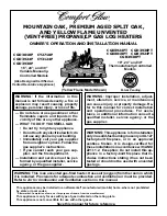
CGB3924PT
Brand: Comfort Glow Pages: 36

Thermopod
Brand: HARNITEK Pages: 28

UHQ-867
Brand: UNITED Pages: 4

Poolex MEGALINE FI
Brand: poolstar Pages: 38


