Repair information
4-157
7562
Go Back
Previous
Next
3.
Determine if the problem is resolved. Do not perform a normal POR until you are sure you have resolved
the problem.
•
If the problem is
not
resolved, then turn the printer off and reinstall the old part.
•
If the problem is resolved, then turn the printer off and turn it back on without holding any buttons
(
perform a normal POR
).
4.
Verify that the input sources are recognized:
a.
From the Home screen, navigate to:
Menus
>
Paper Menu
>
Paper Size/Type
b.
Make sure all installed options are listed.
5.
Verify that the output options are recognized:
a.
From the Home screen, navigate to:
Menus
>
Paper Menu
>
Bin Setup
>
Output Bin
b.
Make sure all installed options are listed.
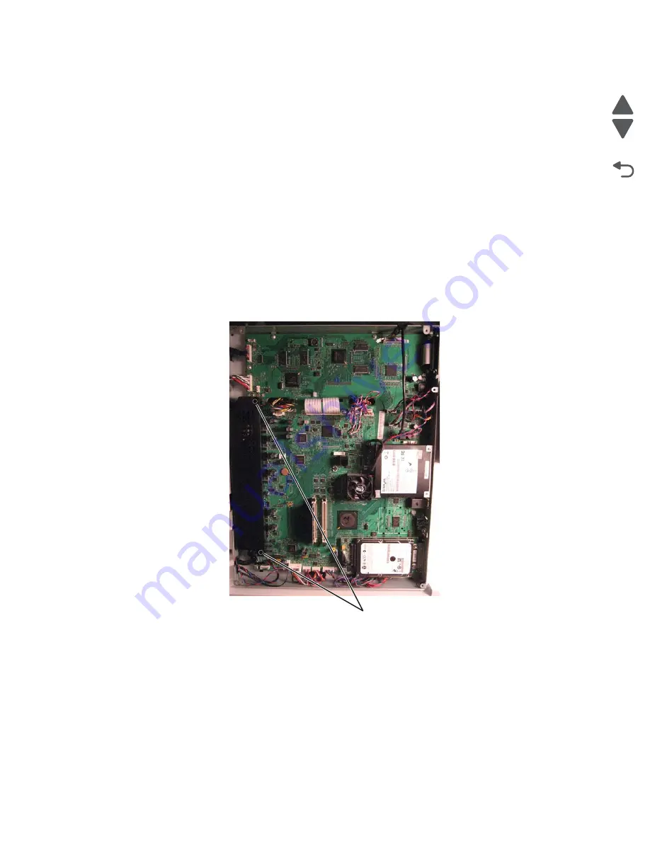
System board cage with board removal
1.
Remove the flatbed scanner assembly. See
“Flatbed scanner assembly removal” on page 4-226
.
2.
Remove the LVPS. See
“Low-voltage power supply (LVPS) removal” on page 4-81
.
3.
Remove two screws (A) to remove the RIP card shield from the system board.
A (88A0232)
Summary of Contents for X792 7562-4xx
Page 21: ...Notices and safety information xxi 7562 Go Back Previous Next ...
Page 22: ...xxii Service Manual 7562 Go Back Previous Next ...
Page 238: ...2 198 Service Manual 7562 Go Back Previous Next ...
Page 396: ...4 90 Service Manual 7562 Go Back Previous Next d Lift the rail out of the printer ...
Page 409: ...Repair information 4 103 7562 Go Back Previous Next Verify the rolls turn freely ...
Page 454: ...4 148 Service Manual 7562 Go Back Previous Next ...
Page 459: ...Repair information 4 153 7562 Go Back Previous Next 7 Remove two screws C C 88A0232 ...
Page 582: ...4 276 Service Manual 7562 Go Back Previous Next 10 Remove the jam clearance cover sensor ...
Page 597: ...Repair information 4 291 7562 Go Back Previous Next 7 Remove the motor from the bracket ...
Page 726: ...4 420 Service Manual 7562 Go Back Previous Next ...
Page 728: ...5 2 Service Manual 7562 Go Back Previous Next Connectors System board ...
Page 738: ...5 12 Service Manual 7562 Go Back Previous Next UICC card ...
Page 747: ...Connector locations 5 21 7562 Go Back Previous Next 5 bin mailbox system card ...
Page 750: ...5 24 Service Manual 7562 Go Back Previous Next ...
Page 754: ...6 4 Service Manual 7562 Go Back Previous Next ...
Page 760: ...7 6 Service Manual 7562 Go Back Previous Next Assembly 3 Front 1 2 4 5 6 7 8 3 3 3 3 ...
Page 762: ...7 8 Service Manual 7562 Go Back Previous Next Assembly 3 1 Front continued 1 2 4 5 1 1 1 3 ...
Page 764: ...7 10 Service Manual 7562 Go Back Previous Next Assembly 4 Left 1 2 5 6 8 7 4 3 ...
Page 766: ...7 12 Service Manual 7562 Go Back Previous Next Assembly 4 1 Left continued 1 2 3 4 ...
Page 768: ...7 14 Service Manual 7562 Go Back Previous Next Assembly 5 Rear 1 4 5 8 10 6 9 2 3 7 11 ...
Page 770: ...7 16 Service Manual 7562 Go Back Previous Next Assembly 5 1 Rear continued 4 6 3 2 1 5 ...
Page 772: ...7 18 Service Manual 7562 Go Back Previous Next Assembly 6 Flatbed scanner ...
Page 774: ...7 20 Service Manual 7562 Go Back Previous Next Assembly 7 ADF unit assembly 1 ...
Page 776: ...7 22 Service Manual 7562 Go Back Previous Next Assembly 8 ADF covers 1 2 4 3 5 6 7 8 9 10 11 ...
Page 782: ...7 28 Service Manual 7562 Go Back Previous Next Assembly 11 Optional 550 sheet tray 2 3 1 ...
Page 794: ...7 40 Service Manual 7562 Go Back Previous Next Assembly 16 Finisher stapler assembly 1 2 ...
Page 798: ...7 44 Service Manual 7562 Go Back Previous Next Assembly 18 5 bin mailbox assembly complete 1 ...
Page 804: ...7 50 Service Manual 7562 Go Back Previous Next Assembly 21 HTU complete 1 ...
Page 812: ...7 58 Service Manual 7562 Go Back Previous Next Assembly 25 HTU with hole punch complete 1 ...
Page 830: ...7 76 Service Manual 7562 Go Back Previous Next ...
Page 832: ...A 2 Service Manual 7562 Go Back Previous Next Print Quality Pages Page 1 total of five ...
Page 834: ...A 4 Service Manual 7562 Go Back Previous Next Print Quality Pages Page 3 total of five ...


