Diagnostic aids
3-45
7562
Go Back
Previous
Next
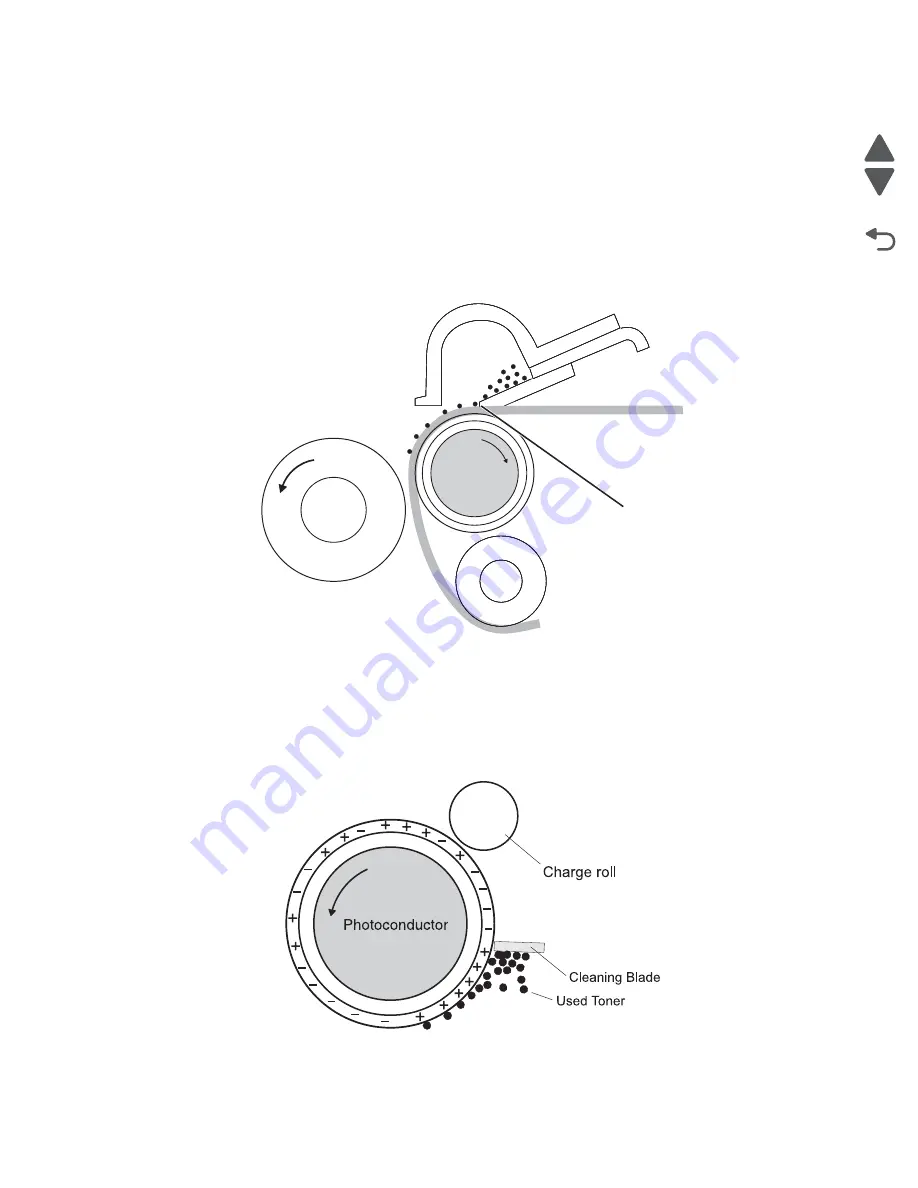
Step 6: Clean/Erase
There are two main cleaning processes that take place during the EP Process. One process cleans the transfer
belt, and the other cleans the photoconductors.
Transfer Unit Clean
Once the toner image on the transfer belt has been transferred to the page, the transfer belt rotates around and
is cleaned by the cleaning blade (G). This occurs for every page that is printed.
After the toner is moved to the cleaning blade, the toner is moved to the waste toner area using an auger
system.
Photoconductor Clean/Erase
After each plane of color has been transferred to the transfer belt from the photoconductors, a cleaning blade
(H) scrapes the remaining toner from the surface of each photoconductor. This is the clean/erase process.
Now the photoconductor surface is prepared to begin the EP Process once again. This cleaning/erasing cycle
happens after each plane of color is transferred to the transfer belt.
Transfer roll
G
Summary of Contents for X792 7562-4xx
Page 21: ...Notices and safety information xxi 7562 Go Back Previous Next ...
Page 22: ...xxii Service Manual 7562 Go Back Previous Next ...
Page 238: ...2 198 Service Manual 7562 Go Back Previous Next ...
Page 396: ...4 90 Service Manual 7562 Go Back Previous Next d Lift the rail out of the printer ...
Page 409: ...Repair information 4 103 7562 Go Back Previous Next Verify the rolls turn freely ...
Page 454: ...4 148 Service Manual 7562 Go Back Previous Next ...
Page 459: ...Repair information 4 153 7562 Go Back Previous Next 7 Remove two screws C C 88A0232 ...
Page 582: ...4 276 Service Manual 7562 Go Back Previous Next 10 Remove the jam clearance cover sensor ...
Page 597: ...Repair information 4 291 7562 Go Back Previous Next 7 Remove the motor from the bracket ...
Page 726: ...4 420 Service Manual 7562 Go Back Previous Next ...
Page 728: ...5 2 Service Manual 7562 Go Back Previous Next Connectors System board ...
Page 738: ...5 12 Service Manual 7562 Go Back Previous Next UICC card ...
Page 747: ...Connector locations 5 21 7562 Go Back Previous Next 5 bin mailbox system card ...
Page 750: ...5 24 Service Manual 7562 Go Back Previous Next ...
Page 754: ...6 4 Service Manual 7562 Go Back Previous Next ...
Page 760: ...7 6 Service Manual 7562 Go Back Previous Next Assembly 3 Front 1 2 4 5 6 7 8 3 3 3 3 ...
Page 762: ...7 8 Service Manual 7562 Go Back Previous Next Assembly 3 1 Front continued 1 2 4 5 1 1 1 3 ...
Page 764: ...7 10 Service Manual 7562 Go Back Previous Next Assembly 4 Left 1 2 5 6 8 7 4 3 ...
Page 766: ...7 12 Service Manual 7562 Go Back Previous Next Assembly 4 1 Left continued 1 2 3 4 ...
Page 768: ...7 14 Service Manual 7562 Go Back Previous Next Assembly 5 Rear 1 4 5 8 10 6 9 2 3 7 11 ...
Page 770: ...7 16 Service Manual 7562 Go Back Previous Next Assembly 5 1 Rear continued 4 6 3 2 1 5 ...
Page 772: ...7 18 Service Manual 7562 Go Back Previous Next Assembly 6 Flatbed scanner ...
Page 774: ...7 20 Service Manual 7562 Go Back Previous Next Assembly 7 ADF unit assembly 1 ...
Page 776: ...7 22 Service Manual 7562 Go Back Previous Next Assembly 8 ADF covers 1 2 4 3 5 6 7 8 9 10 11 ...
Page 782: ...7 28 Service Manual 7562 Go Back Previous Next Assembly 11 Optional 550 sheet tray 2 3 1 ...
Page 794: ...7 40 Service Manual 7562 Go Back Previous Next Assembly 16 Finisher stapler assembly 1 2 ...
Page 798: ...7 44 Service Manual 7562 Go Back Previous Next Assembly 18 5 bin mailbox assembly complete 1 ...
Page 804: ...7 50 Service Manual 7562 Go Back Previous Next Assembly 21 HTU complete 1 ...
Page 812: ...7 58 Service Manual 7562 Go Back Previous Next Assembly 25 HTU with hole punch complete 1 ...
Page 830: ...7 76 Service Manual 7562 Go Back Previous Next ...
Page 832: ...A 2 Service Manual 7562 Go Back Previous Next Print Quality Pages Page 1 total of five ...
Page 834: ...A 4 Service Manual 7562 Go Back Previous Next Print Quality Pages Page 3 total of five ...


