2-64
Service Manual
7562
Go Back
Previous
Next
80 Replace Fuser
•
Show Me
,
View Supplies
, and
Tell Me More
displays additional information.
• Replace the fuser. See
“Fuser assembly removal” on page 4-60
.
Note:
Be sure to reset the fuser count as instructed on the sheet.
• If this does not fix the problem, replace the system board. See
“System board removal”
on page 4-150
.
80 Fuser Missing
• Reinstall the fuser. See
“Fuser assembly removal” on page 4-60
.
• Reseat connectors behind fuser. They may get dislodged and not make good contact
when the fuser is installed.
• Check the cable connectors for damage at the system board and at the LVPS.
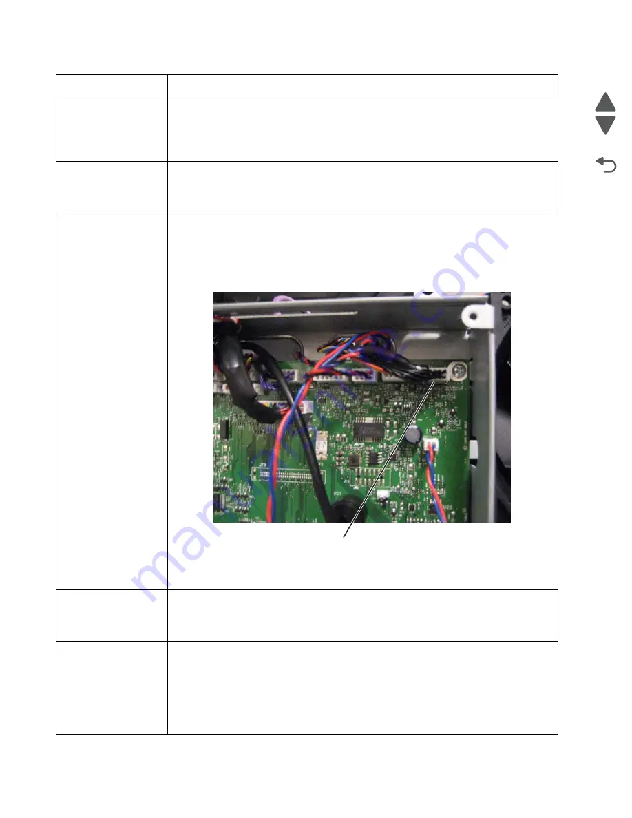
80.41 Fuser missing
• Install the fuser. Replace the fuser if the problem persists.
• If the problem continues, turn the printer off and remove the system board shield. See
“System board shield removal” on page 4-29
. Check the cable in connector JFSR1
(D) for proper connection to the system board, the cable for pinch points, and the cable or
the connector for any other damage. If the connector is damaged on system board,
replace the system board. See
“System board removal” on page 4-150
. If the fuser
cable is damaged, replace the cable.
• Check for continuity in the fuser cable.
If continuity is not present, replace the fuser cable. If the problem persists after replacing
cable, replace the system board. See
“System board removal” on page 4-150
.
82 Waste Toner
Nearly Full
• Select
Continue
to clear the message and continue printing.
• If printing continues, order a replacement waste toner box immediately.
• If the problem persists, open the front access door and check the aligner shaft for binding.
Clear the binding if possible. If not possible, contact your next level of support.
82 Replace Waste
Toner
• Replace the waste toner box using the instruction sheet that comes with the replacement
waste toner box.
• Ensure that there is no interference between the waste toner box and the printer.
• If the problem persists, open the front access door and check the aligner shaft for binding.
Clear the binding if possible.
• If the problem persists, replace the system board. See
“System board removal” on
page 4-150
.
• If the problem persists, contact your next level of support.
Error code
Action
D
Summary of Contents for X792 7562-4xx
Page 21: ...Notices and safety information xxi 7562 Go Back Previous Next ...
Page 22: ...xxii Service Manual 7562 Go Back Previous Next ...
Page 238: ...2 198 Service Manual 7562 Go Back Previous Next ...
Page 396: ...4 90 Service Manual 7562 Go Back Previous Next d Lift the rail out of the printer ...
Page 409: ...Repair information 4 103 7562 Go Back Previous Next Verify the rolls turn freely ...
Page 454: ...4 148 Service Manual 7562 Go Back Previous Next ...
Page 459: ...Repair information 4 153 7562 Go Back Previous Next 7 Remove two screws C C 88A0232 ...
Page 582: ...4 276 Service Manual 7562 Go Back Previous Next 10 Remove the jam clearance cover sensor ...
Page 597: ...Repair information 4 291 7562 Go Back Previous Next 7 Remove the motor from the bracket ...
Page 726: ...4 420 Service Manual 7562 Go Back Previous Next ...
Page 728: ...5 2 Service Manual 7562 Go Back Previous Next Connectors System board ...
Page 738: ...5 12 Service Manual 7562 Go Back Previous Next UICC card ...
Page 747: ...Connector locations 5 21 7562 Go Back Previous Next 5 bin mailbox system card ...
Page 750: ...5 24 Service Manual 7562 Go Back Previous Next ...
Page 754: ...6 4 Service Manual 7562 Go Back Previous Next ...
Page 760: ...7 6 Service Manual 7562 Go Back Previous Next Assembly 3 Front 1 2 4 5 6 7 8 3 3 3 3 ...
Page 762: ...7 8 Service Manual 7562 Go Back Previous Next Assembly 3 1 Front continued 1 2 4 5 1 1 1 3 ...
Page 764: ...7 10 Service Manual 7562 Go Back Previous Next Assembly 4 Left 1 2 5 6 8 7 4 3 ...
Page 766: ...7 12 Service Manual 7562 Go Back Previous Next Assembly 4 1 Left continued 1 2 3 4 ...
Page 768: ...7 14 Service Manual 7562 Go Back Previous Next Assembly 5 Rear 1 4 5 8 10 6 9 2 3 7 11 ...
Page 770: ...7 16 Service Manual 7562 Go Back Previous Next Assembly 5 1 Rear continued 4 6 3 2 1 5 ...
Page 772: ...7 18 Service Manual 7562 Go Back Previous Next Assembly 6 Flatbed scanner ...
Page 774: ...7 20 Service Manual 7562 Go Back Previous Next Assembly 7 ADF unit assembly 1 ...
Page 776: ...7 22 Service Manual 7562 Go Back Previous Next Assembly 8 ADF covers 1 2 4 3 5 6 7 8 9 10 11 ...
Page 782: ...7 28 Service Manual 7562 Go Back Previous Next Assembly 11 Optional 550 sheet tray 2 3 1 ...
Page 794: ...7 40 Service Manual 7562 Go Back Previous Next Assembly 16 Finisher stapler assembly 1 2 ...
Page 798: ...7 44 Service Manual 7562 Go Back Previous Next Assembly 18 5 bin mailbox assembly complete 1 ...
Page 804: ...7 50 Service Manual 7562 Go Back Previous Next Assembly 21 HTU complete 1 ...
Page 812: ...7 58 Service Manual 7562 Go Back Previous Next Assembly 25 HTU with hole punch complete 1 ...
Page 830: ...7 76 Service Manual 7562 Go Back Previous Next ...
Page 832: ...A 2 Service Manual 7562 Go Back Previous Next Print Quality Pages Page 1 total of five ...
Page 834: ...A 4 Service Manual 7562 Go Back Previous Next Print Quality Pages Page 3 total of five ...


