4-60
Service Manual
4060-
xxx
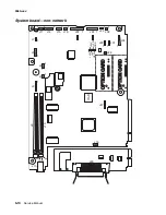
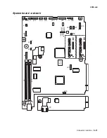
System board installation
Note:
The replacement system board assembly contains a communications board connected to the
system board. To install, you need to separate the boards.
Warning:
Observe all ESD precautions while handling ESD-sensitive parts. See
“Handling ESD-
sensitive parts” on page 4-1
.
1.
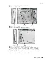
Flex the communications board to separate the boards.
2.
For non-network models, connect the communications board bracket to the communication
board with two screws (A).
3.
Clip the communications board shield ground clip on the frame and insert the communications
card into the interconnect card slot.
4.
Replace the communications board shield mounting screw to connect the bracket to the frame.
5.
Insert the communications board mounting screw.
6.
Install the system board.
7.
Insert the USB screw.
8.
Replace the five mounting screws.
9.
Replace the features/options and reconnect all cables.
A
Summary of Contents for T63 Series
Page 13: ...Laser notices xiii 4060 xxx Japanese Laser Notice ...
Page 14: ...xiv Service Manual 4060 xxx Korean Laser Notice ...
Page 34: ...1 16 Service Manual 4060 xxx ...
Page 218: ...4 64 Service Manual 4060 xxx ...
Page 236: ...6 2 Service Manual 4060 xxx ...
Page 238: ...7 2 Service Manual 4060 xxx Assembly 1 Covers ...
Page 240: ...7 4 Service Manual 4060 xxx Assembly 2 Frame 1 5 2 1 3 4 3 4 8 6 7 ...
Page 252: ...7 16 Service Manual 4060 xxx Assembly 9 Paper feed alignment 3 2 1 4 ...
Page 258: ...7 22 Service Manual 4060 xxx Assembly 12 Drives Main drive and developer drive 3 2 4 1 7 6 5 ...
Page 260: ...7 24 Service Manual 4060 xxx Assembly 13 Hot roll fuser 3 7 5 2 6 4 1 5 8 7 9 ...
Page 262: ...7 26 Service Manual 4060 xxx Assembly 14 Transfer charging 3 2 4 1 5 6 7 9 10 8 ...
Page 264: ...7 28 Service Manual 4060 xxx Assembly 15 Electronics power supplies 3 7 5 2 6 4 1 ...
Page 266: ...7 30 Service Manual 4060 xxx Assembly 16 Electronics card assemblies 3 1 4 5 6 9 2 4 7 8 10 ...
Page 268: ...7 32 Service Manual 4060 xxx Assembly 17 Electronics shields ...
Page 270: ...7 34 Service Manual 4060 xxx Assembly 18 Cabling diagrams 1 3 1 2 4 5 6 7 8 7 4 ...
Page 272: ...7 36 Service Manual 4060 xxx Assembly 19 Cabling diagrams 2 HVPS LVPS 3 5 4 1 2 6 ...
Page 276: ...7 40 Service Manual 4060 xxx Assembly 21 250 sheet paper tray ...
Page 284: ...7 48 Service Manual 4060 xxx Assembly 23 Duplex option 1 ...
Page 286: ...7 50 Service Manual 4060 xxx Assembly 24 Envelope feeder 3 11 7 13 5 9 2 10 6 4 12 8 14 1 ...
Page 288: ...7 52 Service Manual 4060 xxx Assembly 25 Output expander ...
Page 290: ...7 54 Service Manual 4060 xxx Assembly 25 cont Output expander ...
Page 292: ...7 56 Service Manual 4060 xxx Assembly 26 High capacity output expander ...
Page 296: ...7 60 Service Manual 4060 xxx Assembly 27 5 bin mailbox ...
Page 298: ...7 62 Service Manual 4060 xxx Assembly 27 cont 5 bin mailbox ...
Page 300: ...7 64 Service Manual 4060 xxx Assembly 28 High capacity feeder 1 ...
Page 320: ...7 84 Service Manual 4060 xxx Assembly 38 StapleSmart finisher 4 1 ...
Page 344: ...I 20 Service Manual 4060 xxx ...
Page 345: ......

