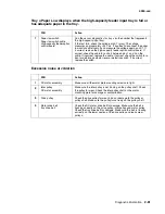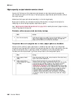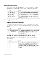
Diagnostic information
2-59
4060-
xxx
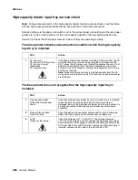
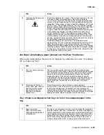
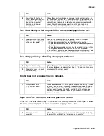
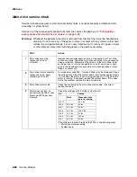
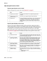
The elevator tray does not move up or down. The printer recognizes that the
option is installed.
The elevator moves in one direction only.
FRU
Action
1
DC drive motor high-
capacity feeder option
system board
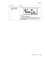
Be sure the motor cable is correctly installed at J1 on the board.
Check the cables, damaged or loose wires. Disconnect the motor.
Check for a short between each pin and the motor housing. If a
problem is found, replace the motor assembly. If no problem is found,
measure the resistance between the following pins on the motor
cable connector:
Pins 1 (brown) and pin 2 (Yellow)
The resistance measures between approximately 7.5 and 10.5 ohms.
If incorrect, replace the motor assembly. If correct, replace the high-
capacity feeder option system board.
FRU
Action
1
DC drive motor assembly
high-capacity feeder
system board
Check the voltages at J1 on the high-capacity system board. The
voltages measure approximately as follows:
If any of the voltages are incorrect, disconnect the motor and
measure the resistance between J-1 and J-2. The resistance
measures between 7.5 and 10.5 ohms. If incorrect, replace the
motor. If correct, replace the system board.
Pin
Color
Voltage
Static (motor not running)
J1-1
Brown
0 V dc
J1-2
Yellow
0 V dc
Motor running forward
J1-1
Brown
0 V dc
J1-2
Yellow
+24 V dc
Motor running in reverse
J1-1
Brown
+24 V dc
J1-2
Yellow
0 V dc
Summary of Contents for T63 Series
Page 13: ...Laser notices xiii 4060 xxx Japanese Laser Notice ...
Page 14: ...xiv Service Manual 4060 xxx Korean Laser Notice ...
Page 34: ...1 16 Service Manual 4060 xxx ...
Page 218: ...4 64 Service Manual 4060 xxx ...
Page 236: ...6 2 Service Manual 4060 xxx ...
Page 238: ...7 2 Service Manual 4060 xxx Assembly 1 Covers ...
Page 240: ...7 4 Service Manual 4060 xxx Assembly 2 Frame 1 5 2 1 3 4 3 4 8 6 7 ...
Page 252: ...7 16 Service Manual 4060 xxx Assembly 9 Paper feed alignment 3 2 1 4 ...
Page 258: ...7 22 Service Manual 4060 xxx Assembly 12 Drives Main drive and developer drive 3 2 4 1 7 6 5 ...
Page 260: ...7 24 Service Manual 4060 xxx Assembly 13 Hot roll fuser 3 7 5 2 6 4 1 5 8 7 9 ...
Page 262: ...7 26 Service Manual 4060 xxx Assembly 14 Transfer charging 3 2 4 1 5 6 7 9 10 8 ...
Page 264: ...7 28 Service Manual 4060 xxx Assembly 15 Electronics power supplies 3 7 5 2 6 4 1 ...
Page 266: ...7 30 Service Manual 4060 xxx Assembly 16 Electronics card assemblies 3 1 4 5 6 9 2 4 7 8 10 ...
Page 268: ...7 32 Service Manual 4060 xxx Assembly 17 Electronics shields ...
Page 270: ...7 34 Service Manual 4060 xxx Assembly 18 Cabling diagrams 1 3 1 2 4 5 6 7 8 7 4 ...
Page 272: ...7 36 Service Manual 4060 xxx Assembly 19 Cabling diagrams 2 HVPS LVPS 3 5 4 1 2 6 ...
Page 276: ...7 40 Service Manual 4060 xxx Assembly 21 250 sheet paper tray ...
Page 284: ...7 48 Service Manual 4060 xxx Assembly 23 Duplex option 1 ...
Page 286: ...7 50 Service Manual 4060 xxx Assembly 24 Envelope feeder 3 11 7 13 5 9 2 10 6 4 12 8 14 1 ...
Page 288: ...7 52 Service Manual 4060 xxx Assembly 25 Output expander ...
Page 290: ...7 54 Service Manual 4060 xxx Assembly 25 cont Output expander ...
Page 292: ...7 56 Service Manual 4060 xxx Assembly 26 High capacity output expander ...
Page 296: ...7 60 Service Manual 4060 xxx Assembly 27 5 bin mailbox ...
Page 298: ...7 62 Service Manual 4060 xxx Assembly 27 cont 5 bin mailbox ...
Page 300: ...7 64 Service Manual 4060 xxx Assembly 28 High capacity feeder 1 ...
Page 320: ...7 84 Service Manual 4060 xxx Assembly 38 StapleSmart finisher 4 1 ...
Page 344: ...I 20 Service Manual 4060 xxx ...
Page 345: ......


