


Preventive maintenance
6-1
4060-
xxx
6. Preventive maintenance
This chapter describes procedures for printer preventive maintenance. Following these
recommendations can help prevent problems and maintain optimum performance.
Safety inspection guide
The purpose of this inspection guide is to aid you in identifying unsafe conditions.
If any unsafe conditions exist, find out how serious the hazard could be and if you can continue
before you correct the hazard.
Check the following items:
•
Damaged, missing, or altered parts, especially in the area of the on/off switch and the power
supply.
•
Damaged, missing, or altered covers, especially in the area of the top cover and the power
supply cover.
•
Possible safety exposure from any non-Lexmark attachments.
Lubrication specifications
No requirements for this printer.
Scheduled maintenance
The operator panel displays the message “80 Scheduled Maintenance” at each 300K page count
interval. It is necessary to replace the fuser assembly, transfer roller, charge roll, and pick tires at this
interval to maintain the print quality and reliability of the printer. The parts are available as a
maintenance kit with the following part numbers:
After replacing the kit, the maintenance count must be reset to zero to clear the “80 Scheduled
Maintenance” message. See
“Maintenance page count” on page 3-17
.
Maintenance kits
Description
Part number
000/010, 200/210
400/410
115 V Maintenance kit
56P1409
56P1855
220 V Maintenance kit
56P1412
56P1856
100 V Maintenance kit
56P1413
56P1857
Summary of Contents for T63 Series
Page 13: ...Laser notices xiii 4060 xxx Japanese Laser Notice ...
Page 14: ...xiv Service Manual 4060 xxx Korean Laser Notice ...
Page 34: ...1 16 Service Manual 4060 xxx ...
Page 218: ...4 64 Service Manual 4060 xxx ...
Page 236: ...6 2 Service Manual 4060 xxx ...
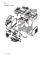
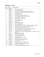
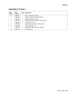
Page 238: ...7 2 Service Manual 4060 xxx Assembly 1 Covers ...
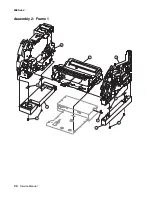
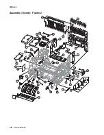
Page 240: ...7 4 Service Manual 4060 xxx Assembly 2 Frame 1 5 2 1 3 4 3 4 8 6 7 ...
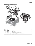
Page 252: ...7 16 Service Manual 4060 xxx Assembly 9 Paper feed alignment 3 2 1 4 ...
Page 258: ...7 22 Service Manual 4060 xxx Assembly 12 Drives Main drive and developer drive 3 2 4 1 7 6 5 ...
Page 260: ...7 24 Service Manual 4060 xxx Assembly 13 Hot roll fuser 3 7 5 2 6 4 1 5 8 7 9 ...
Page 262: ...7 26 Service Manual 4060 xxx Assembly 14 Transfer charging 3 2 4 1 5 6 7 9 10 8 ...
Page 264: ...7 28 Service Manual 4060 xxx Assembly 15 Electronics power supplies 3 7 5 2 6 4 1 ...
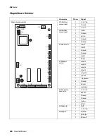
Page 266: ...7 30 Service Manual 4060 xxx Assembly 16 Electronics card assemblies 3 1 4 5 6 9 2 4 7 8 10 ...
Page 268: ...7 32 Service Manual 4060 xxx Assembly 17 Electronics shields ...
Page 270: ...7 34 Service Manual 4060 xxx Assembly 18 Cabling diagrams 1 3 1 2 4 5 6 7 8 7 4 ...
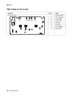
Page 272: ...7 36 Service Manual 4060 xxx Assembly 19 Cabling diagrams 2 HVPS LVPS 3 5 4 1 2 6 ...
Page 276: ...7 40 Service Manual 4060 xxx Assembly 21 250 sheet paper tray ...
Page 284: ...7 48 Service Manual 4060 xxx Assembly 23 Duplex option 1 ...
Page 286: ...7 50 Service Manual 4060 xxx Assembly 24 Envelope feeder 3 11 7 13 5 9 2 10 6 4 12 8 14 1 ...
Page 288: ...7 52 Service Manual 4060 xxx Assembly 25 Output expander ...
Page 290: ...7 54 Service Manual 4060 xxx Assembly 25 cont Output expander ...
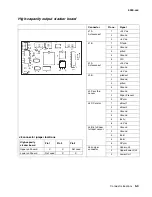
Page 292: ...7 56 Service Manual 4060 xxx Assembly 26 High capacity output expander ...
Page 296: ...7 60 Service Manual 4060 xxx Assembly 27 5 bin mailbox ...
Page 298: ...7 62 Service Manual 4060 xxx Assembly 27 cont 5 bin mailbox ...
Page 300: ...7 64 Service Manual 4060 xxx Assembly 28 High capacity feeder 1 ...
Page 320: ...7 84 Service Manual 4060 xxx Assembly 38 StapleSmart finisher 4 1 ...
Page 344: ...I 20 Service Manual 4060 xxx ...
Page 345: ......