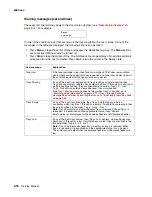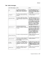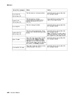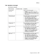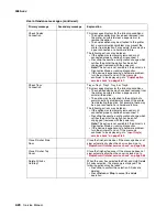
Diagnostic information
2-9
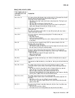
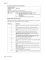
4060-
xxx
84
xx
22
x
1
x
2
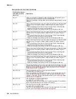
This code indicates that the media activated the input sensor before the printer EP
was ready.
(
x
1=leading edge of media state,
x
2=trailing edge of media state)
84
xx
23
x
1
x
2
The transfer servo never started.
(
x
1=media size,
x
2=leading edge of media state)
84
xx
25
This code indicates that the media has activated the input sensor before the
printhead has locked. Enough time has elapsed since printhead start to expect a
lock.
One of the following may be failing:
• Printhead assembly
• System board
• Printhead cables
84
xx
26
This code indicates that media has activated the input sensor; however, the
printhead fell out of lock condition or not enough time elapsed since the printhead
start to expect a stable lock. The media may have also reached the input sensor
early.
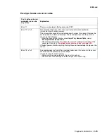
89 00 01
The exit sensor in the fuser is activated by a piece of media indicating there is a
piece of media in the machine during POST.
Check for media in the exit of the fuser assembly or redrive assembly. Feed a
sheet of paper, and if the same error occurs after clearing the fuser or the same
error occurs when no media is present, check the exit sensor assembly, internal
fuser assembly cabling, DC fuser cable to the system board, and the cable
connection to J14 on the system board.
Service tip: Turn the printer off, enter the diagnostic tests menu, and select the
base sensor test. Select output sensor and check the sensor for correct operation.
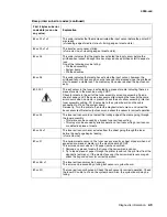
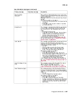
89
xx
03
The fuser exit sensor did not detect the trailing edge of the media going through
the fuser assembly.
• This failure can be caused by a broken fuser exit sensor flag.
• This may also be caused by erratic operation of exit sensor flag or exit sensor
or a defective piece of media.
89
xx
04
x
1
The fuser exit sensor never actuated from the sheet going through the fuser
before the next page begins feeding.
(
x1
=media size)
89
xx
07
The narrow media sensor in the fuser was covered by a sheet of paper when not
expected or a piece of media is in the machine during POST.
This error can occur when a 202 paper jam has occurred.
1. Remove any piece of media that is over the narrow media sensor.
2. Try to feed a piece of paper through the printer (could run the print test from the
diagnostic test menu). If the media stops over the narrow media sensor again,
check the flag and sensor for correct operation.
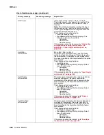
89
xx
0B
x
1
The fuser exit sensor may be bouncing.
This error can be caused by a failing exit sensor or system board.
89
xx
0D
The fuser exit sensor bounced. Check the exit sensor for correct operation. Check
the fuser DC cable to J14 on the system board. Also, the system board may be
failing.
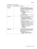
Base printer sub error codes (continued)
First 6 bytes sub error
code data (
xx
can be
any value)
Explanation
Summary of Contents for T63 Series
Page 13: ...Laser notices xiii 4060 xxx Japanese Laser Notice ...
Page 14: ...xiv Service Manual 4060 xxx Korean Laser Notice ...
Page 34: ...1 16 Service Manual 4060 xxx ...
Page 218: ...4 64 Service Manual 4060 xxx ...
Page 236: ...6 2 Service Manual 4060 xxx ...
Page 238: ...7 2 Service Manual 4060 xxx Assembly 1 Covers ...
Page 240: ...7 4 Service Manual 4060 xxx Assembly 2 Frame 1 5 2 1 3 4 3 4 8 6 7 ...
Page 252: ...7 16 Service Manual 4060 xxx Assembly 9 Paper feed alignment 3 2 1 4 ...
Page 258: ...7 22 Service Manual 4060 xxx Assembly 12 Drives Main drive and developer drive 3 2 4 1 7 6 5 ...
Page 260: ...7 24 Service Manual 4060 xxx Assembly 13 Hot roll fuser 3 7 5 2 6 4 1 5 8 7 9 ...
Page 262: ...7 26 Service Manual 4060 xxx Assembly 14 Transfer charging 3 2 4 1 5 6 7 9 10 8 ...
Page 264: ...7 28 Service Manual 4060 xxx Assembly 15 Electronics power supplies 3 7 5 2 6 4 1 ...
Page 266: ...7 30 Service Manual 4060 xxx Assembly 16 Electronics card assemblies 3 1 4 5 6 9 2 4 7 8 10 ...
Page 268: ...7 32 Service Manual 4060 xxx Assembly 17 Electronics shields ...
Page 270: ...7 34 Service Manual 4060 xxx Assembly 18 Cabling diagrams 1 3 1 2 4 5 6 7 8 7 4 ...
Page 272: ...7 36 Service Manual 4060 xxx Assembly 19 Cabling diagrams 2 HVPS LVPS 3 5 4 1 2 6 ...
Page 276: ...7 40 Service Manual 4060 xxx Assembly 21 250 sheet paper tray ...
Page 284: ...7 48 Service Manual 4060 xxx Assembly 23 Duplex option 1 ...
Page 286: ...7 50 Service Manual 4060 xxx Assembly 24 Envelope feeder 3 11 7 13 5 9 2 10 6 4 12 8 14 1 ...
Page 288: ...7 52 Service Manual 4060 xxx Assembly 25 Output expander ...
Page 290: ...7 54 Service Manual 4060 xxx Assembly 25 cont Output expander ...
Page 292: ...7 56 Service Manual 4060 xxx Assembly 26 High capacity output expander ...
Page 296: ...7 60 Service Manual 4060 xxx Assembly 27 5 bin mailbox ...
Page 298: ...7 62 Service Manual 4060 xxx Assembly 27 cont 5 bin mailbox ...
Page 300: ...7 64 Service Manual 4060 xxx Assembly 28 High capacity feeder 1 ...
Page 320: ...7 84 Service Manual 4060 xxx Assembly 38 StapleSmart finisher 4 1 ...
Page 344: ...I 20 Service Manual 4060 xxx ...
Page 345: ......

