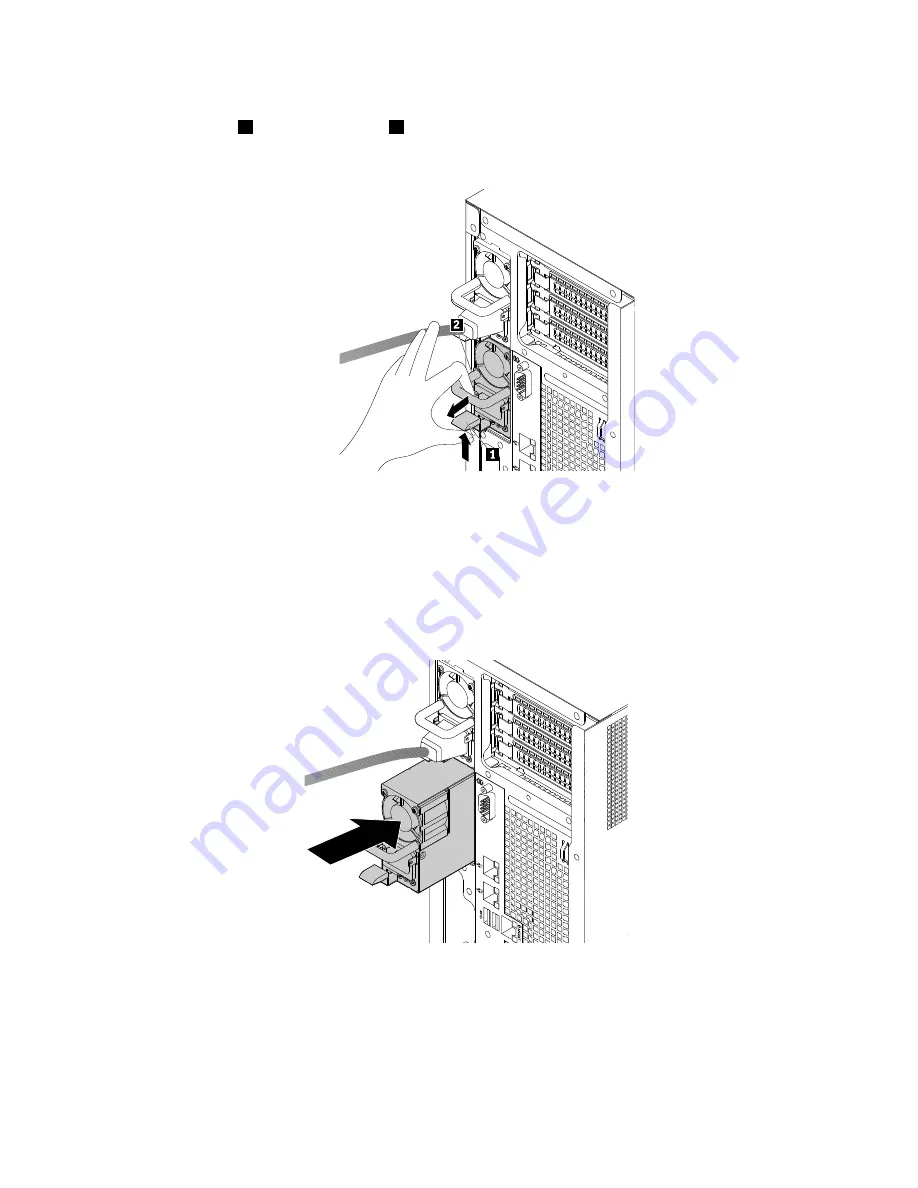
b. Disconnect the power cord from the failing hot-swap redundant power supply. Then, press the
release tab
1
and pull the handle
2
at the same time to slide the failing hot-swap redundant
power supply out of the chassis.
Figure 108. Removing a hot-swap redundant power supply
2. Touch the static-protective package that contains the new hot-swap redundant power supply to any
unpainted surface on the outside of the server. Then, remove the new hot-swap redundant power
supply from the package.
3. Note the orientation of the new hot-swap redundant power supply, and then slide it into the chassis until
it snaps into position.
Figure 109. Installing a hot-swap redundant power supply
4. Connect the power cord to the power cord connector on the new power supply. Then, check the
status LEDs near the power cord connector. For information about the status LEDs, see “Power supply
status LEDs” on page 33.
146
ThinkServer TD350 User Guide and Hardware Maintenance Manual
Summary of Contents for ThinkServer TD350 70DG
Page 14: ...xii ThinkServer TD350 User Guide and Hardware Maintenance Manual ...
Page 18: ...4 ThinkServer TD350 User Guide and Hardware Maintenance Manual ...
Page 20: ...6 ThinkServer TD350 User Guide and Hardware Maintenance Manual ...
Page 66: ...52 ThinkServer TD350 User Guide and Hardware Maintenance Manual ...
Page 192: ...178 ThinkServer TD350 User Guide and Hardware Maintenance Manual ...
Page 202: ...188 ThinkServer TD350 User Guide and Hardware Maintenance Manual ...
Page 217: ...guidelines 69 Copyright Lenovo 2014 2015 203 ...
Page 218: ...204 ThinkServer TD350 User Guide and Hardware Maintenance Manual ...
Page 219: ......
Page 220: ......


