


Page 39 of 60
3-14
For 3-speed spindle moulder with fixed table
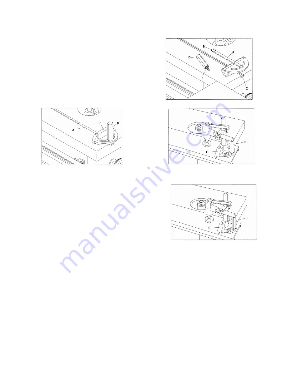
1. Locate the miter gauge bar (A) Fig.3.31, and insert
washer end (B) of bar into T-slot (C) of machine table.
2. Fig.3.32 illustrates the miter gauge bar (A) in the table
slot. Place the miter gauge (F) on the bar. Fasten in place
using washer (E) Fig.3.31 and locking knob (D).
Fig. 3.31
Fig.3.32
Fig.3.33
For 3-speed spindle moulder with sliding table
1. Insert post (A) Fig.3.33 of the clamp assembly down
through hole (B) of the miter gauge body (C), and thread
post (A) into hole (D) of sliding table.
2. Insert shaft of locking handle (E) down through opening (F)
of miter gauge and thread shaft into hole (G) of sliding
table.
3. Fig.3.34, illustrates miter gauge (C) and locking handle (E)
assembled to the sliding table.
Fig. 3.34
ASSEMBLING STOP ROD/FENCE AND STOP TO MITER GAUGE
Stop rod for 5-speed spindle moulder
1. Insert stop rod (A) Fig.3.35, into hole on side of miter gauge body and lock in place with locking knobs
(B).
2. Assemble stop (C) to stop rod (A) as shown, and tighten locking knob (D).
Summary of Contents for S45T
Page 12: ...Page 12 of 60 1 8 Fig 1 1 1 Fig 1 1 2...
Page 13: ...Page 13 of 60 1 9 Fig1 1 3 Fig 1 1 4 1 10 Fig 1 1 5...
Page 48: ...Page 48 of 60 3 24...
Page 49: ...Page 49 of 60 3 25...
Page 54: ...Page 54 of 60 3 30...
Page 61: ......
Page 62: ......
Page 63: ......
Page 64: ......
Page 65: ......
Page 66: ......
Page 67: ......
Page 68: ......
Page 69: ......
Page 70: ......
Page 71: ......
Page 72: ......
Page 73: ......
Page 74: ......
Page 75: ......
Page 76: ......
Page 77: ......
Page 78: ......
Page 79: ......