COMe-mAL10 – User Guide, Rev. 1.3
www.kontron.com
// 62
6.2.3.
Chipset Setup Menu
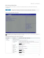
On entering the Chipset Setup menu, the screen lists four sub-screen options North bridge, South bridge, Uncore
Configuration and South Cluster Configuration.
6.2.3.1.
Chipset> North Bridge
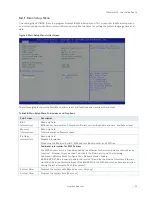
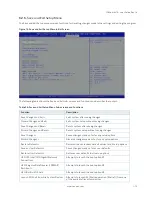
Figure 7: Chipset > North Bridge Menu Initial Screen
The following table shows the North bridge sub-screens and functions and describes the content. Default settings
are in bold.
Table 30: Chipset Set > North Bridge Sub-screens and Function
Function
Second level Sub-Screen / Description
Memory
Configuration>
Read only field
Total memory, Memory slot 0, Memory slot 1, Memory slot 2, Memory slot 3.
Max TOLUD>
Sets the maximum TOLUD value. Dynamic assignment
adjustsTOLUD automatically, based on largest MMIO length of
the installed graphic controller.
[2 GB, 2.25 GB, 2.5 GB, 2,75 GB, 3 GB]
Above 4GB MMIO
BIOS Assignment>
Enables or disables above 4 GB memorymappedIO BIOS
assignment. This is disabled automatically when aperture size is
set to 2048 MB.
[Enabled, Disabled]
PCIE VGA
Workaround>
Enable If PCIe card cannot boot in DOS. For test purposes only.
[Enabled, Disabled]

