COMe-mAL10 – User Guide, Rev. 1.3
www.kontron.com
// 38
4/
System Resources
4.1.
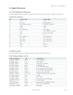
Interrupt Request (IRQ) Lines
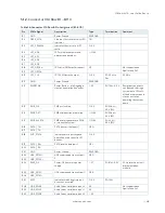
The following table specifies the device connected to each Interrupt line or if the line is available for new devices.
Table 19: Interrupt Requests
IRQ
General Usage
Project Usage
0
Timer
Timer
1
Keyboard
Keyboard (Super I/O)
2
Redirected secondary PIC
Redirected secondary PIC
3
COM2
COM2
4
COM1
COM1
5
LPT2/PCI devices
One of COM3+4
6
FDD
One of COM3+4 or not used
7
LPT1
LPT1 or one of COM3+4
8
RTC
RTC
9
SCI / PCI devices
Free for PCI devices
10
PCI devices
Free for PCI devices
11
PCI devices
Free for PCI devices
12
PS/2 mouse
Free for PCI devices
13
FPU
FPU
14
IDE0
Not used
15
IDE1
Not used
4.2.
Memory Area
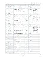
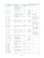
The following table specifies the usage of the address ranges within the memory area.
Table 20: Designated Memory Location
Address Range (hex)
Size
Project Usage
00000000-0009FBFF
639 KB
Real mode memory
0009FC00-0009FFFF
1 KB
Extended BDA
000A0000-000BFFFF
128 KB
Display memory (legacy)
000C0000-000CBFFF
48 KB
VGA BIOS (legacy)
000CC000-000DFFFF
80 KB
Option ROM or XMS (legacy)
000E0000-000EFFFF
64 KB
System BIOS extended space (legacy)
000F0000-000FFFFF
64 KB
System BIOS base segment (legacy)
00100000-7FFFFFFF
128 MB
System memory (Low DRAM)
80000000-FFF00000
2 GB – 1 MB
PCI memory, other extensions (Low MMIO)
FEC00000-FEC00FFF
4 KB
IOxAPIC
FED00000-FED003FF
1 KB
HPET (Timer)
FED40000-FED40FFF
4KB
Always reserved for LPC TPM usage
FEE00000-FEEFFFFF
1MB
Local APIC region
FFFC0000-FFFFFFFF
256 KB
Mapping space for BIOS ROM/Boot vector
100000000-17FFFFFFF
2 GB
System memory (High DRAM)
180000000-F00000000
58 GB
High MMIO


