COMe-mAL10 – User Guide, Rev. 1.3
www.kontron.com
// 42
5/
COMe Interface Connector
The COMe-mAL10 supports one COMe Interface connector (X1A) that is mounted on the bottom side of the module
and contains two rows: row A (1-100) and row B (1-100). The figure below shows the position of the connectors and
indicates the first pin in row A.
Figure 4: X1A COMe Interface Connector
*All dimensions are in mm.
5.1.
X1A Signals
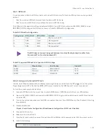
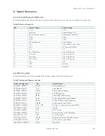
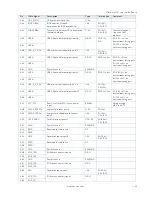
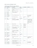
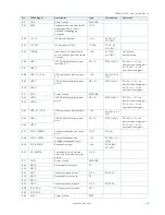
The terms used in the connector pin assignment tables and a description of the signal type can be found in
Table 24: General Signal Description. If more information is required, the Appendix at the end of this user guide and
the PICMG specification COMe Rev 2.1 Type 10 standard, contain additional information.
The information within the COMe Interface connectors pin assignment tables is
complimentary to the COM.0 Rev 2.1 Type 6 standard. For more information, contact
Kontron Support.
Pin
A1
X1A


