COMe-mAL10 – User Guide, Rev. 1.3
www.kontron.com
// 44
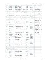
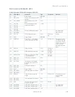
5.1.1.
Connector X1A Row A 1 - A110
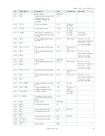
Table 25: Connector X1A Row A Pin Assignment (A1-A110)
Pin
COMe Signal
Description
Type
Termination
Comment
A1
GND
Power Ground
PWR GND
A2
GBE0_MDI3-
Ethernet Media Dependent Interface 3
DP-I/O
A3
GB
A4
GBE0_LINK100#
Ethernet speed LED indicator
OD
A5
GBE0_LINK1000#
A6
GBE0_MDI2-
Ethernet Media Dependent Interface 2
DP-I/O
A7
GB
A8
GBE0_LINK#
LAN link LED indicator (LED)
OD
A9
GBE0_MDI1-
Ethernet Media Dependent Interface 1
DP-I/O
A10
GB
A11
GND
Power Ground
PWR GND
A12
GBE0_MDI0-
Ethernet Media Dependent Interface 0
DP-I/O
A13
GB
A14
GBE0_CTREF
Reference voltage for Carrier Board
Ethernet magnetics center tab. The
reference voltage is determined by the
requirements of the Module PHY and
may be as low as 0V and as high as
3.3V.
O
1 nF capacitor to GND
A15
SUS_S3#
Indicates system is in Suspend to RAM
(or deeper) state. An inverted copy of
SUS_S3# on Carrier Board may be used
to enable
non-standby power on a typical ATX
supply.
O-3.3
PD 10 k
Ω
A16
S
SATA transmit data pair 0
DP-O
A17
SATA0_TX-
A18
SUS_S4#
Indicates system is in Suspend to Disk
(or deeper) state
O-3.3
PD 10 k
Ω
A19
S
SATA receive data pair 0
DP-I
A20
SATA0_RX-
A21
GND
Power Ground
PWR GND
A22
USB_SSRX0-
USB super speed receive data pair 0
DP-I
A23
US
A24
SUS_S5#
Indicates system is in Soft Off state
O-3.3
A25
USB_SSRX1-
USB super speed receive data pair 1
DP-I
A26
US
A27
BATLOW#
Provides a battery-low signal to the
module to indicate external battery is
low
I-3.3
PU 10 k
Ω
,
3.3 V (S5)
Assertion prevents
wake from S3-S5 state
A28
ATA_ACT#
Serial ATA activity LED indicator
OD-3.3
PU 10 k
Ω
,
3.3 V (S0)
Can sink 15 mA
A29
HDA_SYNC
HD Audio Sync
O-3.3
A30
HDA_RST#
HD Audio Reset
O-3.3
A31
GND
Power Ground
PWR GND
A32
HDA_CLK
HD Audio Bit Clock Output
O-3.3


