COMe-mAL10 – User Guide, Rev. 1.3
www.kontron.com
// 26
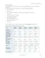
The following table provides the ATX mode settings.
Table 8: ATX Mode Settings
State
PWRBTN#
PWR_OK
V5_StdBy
PS_ON#
VCC
G3
x
x
0V
x
0V
S5
high
low
5V
high
0V
S5
→
S0
PWRBTN Event
low
→
high
5V
high
→
0V
→
VCC
S0
high
high
5V
low
VCC
x – Defines that there is no difference if connected or open.
2.4.4.2.
Single Supply Mode
In single supply mode, without 5V standby the module starts automatically when VCC power is connected and the
Power Good input is open or at high level (internal PU to 3.3 V).
PS_ON# is not used in this mode and VCC can be 4.75 V to 20 V.
To power on the module from S5 state, press the power button or reconnect VCC. Suspend/Standby states are not
supported in single supply mode.
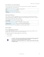
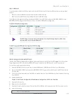
The following table provides the single supply mode settings.
Table 9: Single Supply Mode Settings
State
PWRBTN#
PWR_OK
V5_StdBy
VCC
G3
0V/x
0V/x
0V/x
0V/x
G3
→
S0
high
open / high
open
connecting VCC
S5
high
open / high
open
VCC
S5
→
S0
PWRBTN Event
open / high
open
reconnecting VCC
x – Defines that there is no difference if connected or open.
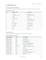
All ground pins must be connected to the carrier board’s ground plane.

