Fuel and lubricants..............................................3-184
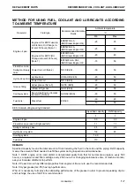
Fuel and lubricants to match the ambient temperature
.........................................................................4-3
Fuel circuit - Bleed air......................................... 3-188
Fuel consumption gauge - Set display..................3-40
Fuel consumption record - Check......................... 3-38
Fuel control dial.....................................................3-64
Fuel gauge............................................................ 3-29
Fuel injection system - Check / Clean...................4-74
Fuel level caution lamp......................................... 3-18
Fuel main filter cartridge - Replace....................... 4-53
Fuel prefilter cartridge - Replace...........................4-51
Fuel prefilter element - Clean................................4-24
Fuel system and cooling system hoses - Check and
replace........................................................... 4-73
Fuel tank - Drain water and sediment................. 3-102
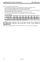
Fuel, coolant and lubricants according to ambient
temperature - Use............................................7-7
Function of accumulator........................................4-69
Function switches................................................. 3-33
Function switches and guidance icons................. 3-31
Fuse...................................................................... 3-81
Fusible link............................................................ 3-82
G
Gas spring - Check............................................... 4-40
Gauge display....................................................... 3-29
General attachment such as crusher etc - Operate.....
.......................................................................6-24
General attachment such as crusher, etc. - Check
points when using.......................................... 6-23
General precautions common to operation and main-
tenance.......................................................... 2-15
General view........................................................... 3-2
GPS synchronization - Set....................................3-55
Grease.................................................................... 4-5
Grease pump holder............................................. 3-83
Ground whole the bottom side of blade to support
machine....................................................... 3-146
Guide to reduce vibration levels on machine.......... 1-9
H
Handle oil, fuel, coolant, and performing oil clinic...4-4
Handling bucket with hook.................................... 6-13
Handling quick coupler............................................6-4
High-pressure hoses and pipings - Handle...........2-42
Horn - Check....................................................... 3-112
Horn switch........................................................... 3-66
Hydraulic breaker..................................................6-41
Hydraulic circuit - Bleed air............................. 4-3,4-41
Hydraulic circuit - Release internal pressure........ 4-72
Hydraulic circuit (2nd line) - Connect.................... 6-27
Hydraulic components - Handle..............................4-7
Hydraulic oil filter element - Replace.................... 4-60
Hydraulic quick coupler system caution lamp....... 3-23
Hydraulic system - Warm-up operation...............3-125
Hydraulic system caution lamp............................. 3-19
Hydraulic tank - Change oil / Clean strainer......... 4-65
Hydraulic tank - Check oil level / Add oil.............3-104
Hydraulic tank breather element - Replace...........4-58
I
If any problem is found..........................................2-16
If machine monitor shows warning display......... 3-198
Inducement strategy when abnormalities are detected
in the NOx control System............................. 3-97
Injector - Check and clean.................................... 4-74
Inside operator's compartment............................. 2-16
Inspecting machine............................................... 2-15
Intake/exhaust throttle valve - Check and test...... 4-74
Introduction........................................................... 1-11
Investigate and confirm jobsite conditions............ 2-22
J
Jumper cable - Connect......................................3-194
Jumper cable - Disconnect................................. 3-195
K
KDPF - Clean........................................................4-76
KDPF soot accumulation caution lamp................. 3-20
KDPF system caution lamp...................................3-19
Keep machine clean............................................. 2-16
Komatsu Diesel Particulate Filter (KDPF) - Handle.....
.......................................................................3-86
Komatsu genuine lubricants....................................4-2
Komatsu genuine replacement parts...................... 4-2
Komatsu machine operator privacy policy.............. 1-3
KOMTRAX............................................................ 3-99
L
Lamp switch.......................................................... 3-66
Language settings.................................................3-59
Left front mirrors - Adjust.....................................3-115
Left front mirrors (Road homologation) - Adjust.. 3-116
Leveling work...................................................... 3-152
Lifting of personnel prohibited...............................2-18
Lifting operation by using bucket with hook.......... 2-32
Lifting operation by using lifting device................. 2-33
Loading and unloading with trailer...................... 3-176
Loading work.......................................................3-152
Location of engine number plate...........................1-15
Location of product identification number (PIN)/
machine serial No. plate................................ 1-15
Location of safety labels......................................... 2-3
Lock.................................................................... 3-158
Lock inspection cover............................................. 4-3
Lock lever..............................................................3-71
Lock lever automatic lock cancel pilot lamp..........3-28
Lock lever automatic lock cancel switch............... 3-69
Lock lever pilot lamp............................................. 3-28
Lubrication chart..................................................... 7-4
INDEX
8-3
WENAM00241
Summary of Contents for PC80MR-5E0
Page 2: ......
Page 12: ...Do not repeatedly handle and lift loads VIBRATION LEVELS FOREWORD 1 10 WENAM00241...
Page 70: ...GENERAL VIEW MACHINE EQUIPMENT NAME RKA67920 GENERAL VIEW OPERATION 3 2 WENAM00241...
Page 76: ...11 Fusible link 12 Ashtray if equipped 13 Tool boxes GENERAL VIEW OPERATION 3 8 WENAM00241...
Page 343: ...SPECIFICATIONS 5 1 WENAM00241...
Page 394: ...WENAM00241...
Page 395: ...REPLACEMENT PARTS 7 1 WENAM00241...
Page 411: ......
Page 412: ......

