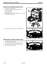
6) Set the lock lever to LOCK position (L).
7) Stop the engine.
REMARK
When removing the pins, place the bucket so that it is in
light contact with the ground.
If the bucket contacts strongly to the ground, the resist-
ance at pins will be increased and it will be difficult to re-
move the pins.
2.
Remove the double nut of stopper bolt at arm pin (A) and
link pin (B), then pull out the bolts.
3.
Pull out arm pin (A) and link pin (B), then remove bucket
(1).
REMARK
When removing the pins, collect the shims that might be
present between the bucket and the arm or link.
4.
Align arm (2) with hole (4) of the replacement bucket.
5.
Align link (3) with hole (5) of the replacement bucket.
6.
Apply grease to pins (A) and (B) and insert them together
with the shims found during disassembly into holes (4)
and (5) of the bucket.
REMARK
• Perform installation in the reverse order to removal.
• Verify the play of bucket. For detail see MAINTE-
NANCE “METHOD FOR ADJUSTING BUCKET AX-
IAL PLAY”.
After inserting pin (A) and (B), fit it in the regular
groove.
7.
Install the lock bolt and nut of each pin.
8.
Apply grease to each pin.
REMARK
Lubricate with grease thoroughly from the grease nipple until the grease comes out from the end face of
pin.
MACHINE OPERATIONS AND CONTROLS
OPERATION
3-156
WENAM00241
Summary of Contents for PC80MR-5E0
Page 2: ......
Page 12: ...Do not repeatedly handle and lift loads VIBRATION LEVELS FOREWORD 1 10 WENAM00241...
Page 70: ...GENERAL VIEW MACHINE EQUIPMENT NAME RKA67920 GENERAL VIEW OPERATION 3 2 WENAM00241...
Page 76: ...11 Fusible link 12 Ashtray if equipped 13 Tool boxes GENERAL VIEW OPERATION 3 8 WENAM00241...
Page 343: ...SPECIFICATIONS 5 1 WENAM00241...
Page 394: ...WENAM00241...
Page 395: ...REPLACEMENT PARTS 7 1 WENAM00241...
Page 411: ......
Page 412: ......


