background image

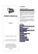
Service
Manual

JS70

from machine no. 695501

PUBLISHED BY THE

TECHNICAL PUBLICATIONS DEPARTMENT

OF JCB SERVICE: ©

ROCESTER, STAFFORDSHIRE, ST14 5LS,

ENGLAND

Tel. ROCESTER (01889) 590312

PRINTED IN ENGLAND

Publication No. 9803/6020

R

General Information

Care & Safety

Routine Maintenance

Attachments

Body & Framework

Electrics

1

2

3

A

B

C

Hydraulics

E

F

Transmission

G

Brakes

J

Track & Running Gear

K

Engine

Issue 0

Summary of Contents for JS70

Page 1: ...CB SERVICE ROCESTER STAFFORDSHIRE ST14 5LS ENGLAND Tel ROCESTER 01889 590312 PRINTED IN ENGLAND Publication No 9803 6020 R General Information Care Safety Routine Maintenance Attachments Body Framewor...

Page 2: ...nings and cautions pertinent to aspects of workshop procedures etc 3 Routine Maintenance includes service schedules and recommended lubricants for the whole machine The remaining sections are alphabet...

Page 3: ...Specifications 1 1 General Torque Settings 1 2 Service Tools Section C Electrics 4 1 Section E Hydraulics 5 1 Section F Transmission 6 1 Sealing and Retaining Compounds 7 1 i General Information 9803...

Page 4: ...7 4 46 54 4 Upper Carrier Roller M16 24 267 312 27 2 31 8 197 230 5 Lower Track Roller M12 19 109 127 11 13 80 94 6 Grease Cylinder M12 19 109 127 11 13 80 94 7 Track Guard M12 19 109 127 11 13 80 94...

Page 5: ...lbf ft M3 0 39 0 04 0 28 M4 0 78 0 08 0 57 M5 1 67 0 17 1 2 M6 2 84 0 29 2 1 8 04 0 82 5 9 11 3 1 15 8 3 M8 7 06 0 72 5 2 19 6 2 00 14 5 27 7 2 82 20 4 M10 14 0 1 43 10 3 39 1 3 99 28 8 55 0 5 61 40...

Page 6: ...TRICS Electrical Test Equipment 1 892 00283 Tool Kit Case 2 892 00281 AVO Meter 3 892 00286 Surface Temperature Probe 4 892 00284 Microtach Digital Tachometer 5 892 00282 Shunt open type 6 892 00285 H...

Page 7: ...x Test Point 892 00267 1 1 2 in M BSP x 1 1 2 in F BSP x Test Point Pressure Test Adapters 892 00255 1 4 in BSP x Test Point 892 00256 3 8 in BSP x Test Point 892 00257 1 2 in BSP x Test Point 892 00...

Page 8: ...92 00278 Gauge 0 40 bar 0 600 lb in2 892 00279 Gauge 0 400 bar 0 6000 lb in2 892 00280 Gauge 0 600 bar 0 8500 lb in2 816 50005 1 2 in BSP A x 1 2 in BSP B 816 60096 3 4 in BSP A x 3 4 in BSP B 816 000...

Page 9: ...993 99524 Ram Eye End Modification Plate Assembly 556 43400 Lift Ram 545 18000 Lynch Pin 811 50232 1 1 4 in Pivot Pin Ram Piston Nut Removal Fitting Spanner 993 99512 Spanner 55mm A F 993 99513 Spanne...

Page 10: ...5 4 Section 1 General Information 9803 6020 Section 1 5 4 Issue 1 Service Tools continued SECTION E HYDRAULICS Seal press fit jig Seal protector...

Page 11: ...ection 1 5 5 Issue 1 Service Tools continued SECTION E HYDRAULICS Jig to press fit the taper roller bearing inner rings Barrel pulling out jig Hanger assembling jig More than 140 Approximate Hexagon s...

Page 12: ...ecial Tool II For removing the deep groove ball bearing race 149 from shaft 102 Special tool III for pressing the oil seal 132 into the spindle Special tool IV Use to locate the outer race of the bear...

Page 13: ...eter upwards e g suction strainer 4101 0451 50 ml JCB Threadlocker Sealer A medium to high strength locking fluid 4101 0552 High Strength JCB Threadseal Medium strength thread sealant for patch bolts...

Page 14: ...Contents Page No Safety Notices 1 1 General Safety 2 1 Operating Safety 3 1 Maintenance Safety 4 1 i Care Safety 9803 6020 i Issue 1 Section 2 Section 2...

Page 15: ...per precautions are not taken it is highly probable that the operator or others could be killed or seriously injured INT 1 2 1 WARNING Denotes a hazard exists If proper precautions are not taken the o...

Page 16: ...1 3 7 WARNING Clothing You can be injured if you do not wear the proper clothing Loose clothing can get caught in the machinery Wear protective clothing to suit the job Examples of protective clothin...

Page 17: ...king sure there is good ventilation If possible fit an exhaust extension If you begin to feel drowsy stop the machine at once Get out of the cab into fresh air INT 2 1 10 WARNING Hazardous Atmospheres...

Page 18: ...contaminated with oil thoroughly in warm soapy water Do not use petrol diesel fuel or paraffin to clean your skin INT 3 2 3 WARNING Fires If your machine is equipped with a fire extinguisher make sur...

Page 19: ...hile the hoses are open INT 3 1 11 1 WARNING Hydraulic Fluid Fine jets of hydraulic fluid at high pressure can penetrate the skin Do not use your fingers to check for hydraulic fluid leaks Do not put...

Page 20: ...ng from hydraulic pump 5 2 Air bleeding from the slew motor 5 3 Air bleeding from ram 5 3 Changing the Fluid 5 4 Changing the Return Filter Element 5 5 Cleaning Changing the Suction Strainer 5 5 Chang...

Page 21: ...the Coolant 8 5 Cleaning the Radiator and Oil Cooler 8 5 Checking the Fan Belt Tension 8 6 Fitting a New Fan Belt 8 6 Draining Fuel Tank Impurities 8 7 Draining the Water Separator 8 7 Changing the Fu...

Page 22: ...Gear Oil HD90 API GL 5 MIL L 2105C 2 x 1 7 litres 0 37 UK gal TRACK ROLLERS AND IDLER WHEEL Engine Oil see separate chart HYDRAULIC SYSTEM JCB Special Hydraulic Vickers 35VQ25 V104C 92 litres Fluid HP...

Page 23: ...open or unlabelled containers Handling New Oil There are no special precautions needed for the handling or use of new oil beside normal care and hygiene practices Used Oil Used engine crankcase lubric...

Page 24: ...perating hours involving use of the breaker When a breaker is fitted ensure that the oil and filters are changed at the intervals shown in the table below The hydraulic oil must be sampled and checked...

Page 25: ...er severe conditions from new will affect its performance and shorten its service life 1 Carry out the Daily inspection procedure 2 Always warm up the machine sufficiently 3 Hold the engine speed to 8...

Page 26: ...Grease a All pivot pins Every 100 Operating Hours or 2 Weekly Whichever occurs first 1 Do a 50 hour service plus 2 Clean a Battery terminals b Fuel lift pump strainer 3 Change a Engine oil main filter...

Page 27: ...peration of overload warning c Operation of stop control Every 1000 Operating Hours or 6 Monthly Whichever occurs first 1 Do a 500 hour service plus 2 Clean a Fuel lift pump strainer b Hydraulic fluid...

Page 28: ...1000 hour service plus 2 Change a Hydraulic oil b Hydraulic tank air breather element c Hydraulic fluid suction strainer Refer to Service intervals for Hydraulic Oil and Filters when using a Breaker...

Page 29: ...t the end of this section 1 Make the Machine Safe Stop the engine and remove the starter key 2 Grease the Slew Ring a Remove cover A and discharge port plug B b Apply grease to the slew ring via apert...

Page 30: ...ut greasing at the beginning of this section Each arrow highlights one grease point 19 Grease points WARNING You will be working close into the machine for these jobs Lower the attachments if possible...

Page 31: ...eginning of this section Each arrow highlights one grease point 27 Grease points WARNING You will be working close into the machine for these jobs Lower the attachments if possible Remove starter key...

Page 32: ...ine in a well ventilated area Switch the charging circuit off before connecting or disconnecting the battery When you have installed the battery in the machine wait five minutes before connecting it u...

Page 33: ...2 Check the Level Look at the fluid level in the sight tube B The level should be between the two marks on the tube If the fluid is cloudy water or air has entered the system Water or air in the syst...

Page 34: ...of this section 3 Temporarily loosen air bleeding plug A 4 If oil comes out re tighten the plug If oil does not come out remove the air bleeding plug A and prime the pump by pouring hydraulic oil into...

Page 35: ...ine on level ground Stop the Engine 2 Locate the Slew Motor The slew motor is mounted on the slew gearbox Refer to the Component Location Diagram at the end of this section 3 Bleeding the Slew Motor a...

Page 36: ...aining oil from the tank into a suitable drain pan 5 Renew the Suction Strainer D and Return Filter E See Cleaning Changing the Suction Strainer and Changing the Return Filter 6 Tighten drain plug C s...

Page 37: ...cover O ring B Cleaning Changing the Suction Strainer 1 Prepare the Machine Position the machine on level ground Stop the engine Remove the starter key 2 Locate the Suction Strainer 3 Release the Tan...

Page 38: ...er element F carefully and remove Take care not to drop any sediment 5 Fit a New Element a Peel off the 4 foil seals of the new Nephron filter element F one on the lower side two on the sides and one...

Page 39: ...old filter element D together with sponge packing E c Install a new filter element D followed by new sponge packing E 5 Refit Filter Cover C Rotate the cover so that it fits over the stud Then in orde...

Page 40: ...r 4 Dismantle the Filter a Using a wrench on the case unscrew filter case A from filter head B Take care not to spill the oil it contains b Remove and discard element C and O ring D 5 Clean the Filter...

Page 41: ...A BLOCKED FILTER 1 Prepare the Machine Position the machine on level ground Stop the engine Remove the starter key 2 Release Tank Pressure See Releasing Tank Pressure 3 Locate the Filter 4 Remove the...

Page 42: ...in the Oil on One Side a Place a container below drain plug C to catch the oil The container must be large enough to hold the maximum gearbox capacity see Fluids and Lubricants Capacities and Specific...

Page 43: ...nent Location Diagram at the end of this section 3 Remove Air Bleed Plug A Note The arrow on the illustration indicates the front of the machine CAUTION Failure to remove the bleed plug before adding...

Page 44: ...the offset boom if fitted to its central position Open the bucket and swing the boom until it is at 90 to the track Lower the bucket to the ground 2 Raise the Track Operate the boom and dipper contro...

Page 45: ...Plates 180 205 Rubber Plates 125 135 Soft Sand Sticky Mud 250 275 3 Adjust the Track Tension WARNING When opening the check valve always stand to one side and loosen a little at a time until grease s...

Page 46: ...ft Checking the Rollers and Idler Wheels for Oil Leaks 1 Prepare the Machine See Clean the Tracks steps 1 to 3 Block the undercarriage 2 Look for Oil Leaks Check the top and bottom rollers and the id...

Page 47: ...e Remove the starter key 3 Open the Engine Hood 4 Remove the End Cover Undo knob A Remove the end cover B 5 Remove the Outer Element Unscrew nut C Pull out the element D Take care not to tap or knock...

Page 48: ...8 Clean the Canister Clean the inside of the canister D the end cover H and dust valve F 9 Fit the New Inner Element Carefully insert the new inner element into the canister Make sure it seats correc...

Page 49: ...be stripped b German machines only Obtain from the tool box the drain tube Remove the sump drain valve dust cover from location C In its place after locating the drain tube inside the oil collecting c...

Page 50: ...efit the Pressure Cap A Make sure it is tight Note Check the quality of the antifreeze mixture every year before the cold weather starts Change it every two years Coolant Mixtures To prevent the coola...

Page 51: ...sing the necessary mix of clean soft water and antifreeze see Coolant Mixtures fill via the expansion bottle cap until the level in the bottle is between the FULL and LOW marks 6 Refit the Radiator Pr...

Page 52: ...t the fan belt tension Note If the fan belt is stretched so much that it cannot be adjusted correctly fit a new belt b When correct tension is achieved fully tighten C and D Fitting a New Fan Belt 1 P...

Page 53: ...nd refit cover B WARNING Fuel oil is highly inflammable Completely wipe off any spilt fuel which could cause a fire 8 3 4 3 Draining the Water Separator The water separator should be drained at least...

Page 54: ...hten onto filter head Use a chain wrench to tighten by a further 2 3 turn Cleaning the Lift Pump Strainer 1 Stop the Engine Switch off the engine and remove the key 2 Disconnect the battery 3 Open the...

Page 55: ...e negative lead to chassis 3 Open the Engine Compartment Locate bleed plug A and priming pump C 4 Prepare for Bleeding Loosen bleed plug A on the fuel filter head Release knob B on the priming pump C...

Page 56: ...18 Expansion bottle 19 Air cleaner 20 Counter weight 21 Revolving frame 22 Battery 23 Slew gearbox 24 Traction equipment 25 Shoe 26 Upper roller 27 Lower roller 28 Recoil spring 29 Idler wheel 30 Rota...

Page 57: ...Contents Page No Weights Weights 1 1 i Body Framework 9803 6020 i Issue 1 Contents Section B Section B...

Page 58: ...6700 14773 G Attachment 1075 2370 B Upper mechanism 3115 6868 H Boom 620 1367 Includes including ram Counterweight and I Dipper 250 551 Slew ring including ram and link C Counterweight 700 1543 J Buck...

Page 59: ...0 mm grouser shoe assembly 582 kg 1283 lb 8 Slew mechanism 176 kg 388 lb 9 Slew ring bearing 100 kg 220 lb 10 Counterweight 700 kg 1543 lb 11 Engine 247 kg 545 lb 12 Radiator 37 kg 82 lb 13 Hydraulic...

Page 60: ...8 Electrical Equipment Layout 3 9 Cab Relays 3 10 Engine Control Basic Operation of Engine Control 4 1 One Touch Idle Control 4 3 Speed Control for Each Mode 4 4 Emergency Stop 4 5 Swing Brake Swing...

Page 61: ...1 1 Section C Electrics 9803 6020 Section C 1 1 Issue 1 Torque Specifications Torque Specifications Component Nm kgfm lb ft Battery securing bolts 19 6 29 4 2 3 14 46 21 69...

Page 62: ...itch 10 A 2 Ignition Switch 10 A 3 Air Conditioning Blower if fitted 20 A Heater 4 Working Lights 15 A 5 Spare 15 A 6 Working Lights Optional 15 A 7 Spare 15 A 8 Windscreen Wiper Washer 10 A 9 Horn 10...

Page 63: ...should not vary between cells by more than 0 04 A greater variation indicates an internal fault on that particular cell If the electrolyte temperature is other than 15 C 60 F a correction factor must...

Page 64: ...Relay LeverLock 14 Cab Wiper Light 15 Fuse Box 16 Starter Switch 17 Fuse 18 Fuse 19 Relay Battery 20 Battery 21 Battery 22 Relay Safety 23 Relay Heating 24 Washer Tank 25 Horn 26 Working Lights House...

Page 65: ......

Page 66: ...ntrol 3 Display Monitor 4 Dozer Blade Lever 5 Rockbreaker Offset Boom Control Pedal 6 Right Hand Track Control 7 Left Hand Track Control 8 Travel Speed Range Change Switch 9 Left Excavator Joystick Co...

Page 67: ...provides progressive engine speed control over the full range 3 Buzzer Silencing Switch Press the switch to silence the warning buzzer Check the items indicated on the monitor and repair or inspect a...

Page 68: ...Wiper Switch The switch that controls the windshield wiper Using the wipers when the windshield is dry or when it is soiled with dirt or with snow can cause damage to the blades Please use caution in...

Page 69: ...Lock Lever Raising lever 1 provides a method of isolating the hydraulic controls in addition to operating the Servo Isolator Switch paragraph 5 and is an integral part of the procedure for vacating th...

Page 70: ...raising the Control Lock Lever paragraph 1 When the switch is pressed the controls are isolated and the Monitor displays the switch icon Press the switch again to reactivate the controls and extinguis...

Page 71: ...minates and the buzzer sounds until pre heating is completed 2 Travel Mode Indicator At ignition switch on the lamp is not lit to indicate that the low speed travel mode is selected When the high spee...

Page 72: ...0 Overheat Warning Illuminates if the engine coolant or hydraulic oil temperature exceeds the preset maximum permissible Check the water temperature gauge 6 to determine if the coolant temperature is...

Page 73: ...a pressure reducing valve dependent on the brake selection Starter switch OFF and SW ON 100 swing lock During engine running and operation other than swing 50 swing lock Swing operation 0 Swing Brake...

Page 74: ...e Motor 6 Oil Temperature Overheat Switch 7 Oil Pressure Switch 8 Water Temperature Thermo Sensor 9 Water Temperature Overheat Switch 10 Heat Relay 11 Starter Relay 12 Battery Relay 13 Fusible Link 14...

Page 75: ...Relays A B C D E F G L K J H M N A Relay Engine Shutdown B Relay Working Lights Boom mounted C Relay Wiper D Relay Lever Lock E Relay Fan 3 F Relay Fan 1 G Relay Fan 2 H Relay Horn J Relay Washer K R...

Page 76: ...Stop Input N Throttle Motor P Potentiometer Q Motor Driver R Throttle Switch 1Potentiometer 2 Potentiometer 3 Throttle Switch Input 4 L Mode 5 Air Con 6 Potentiometer Input 7 Throttle Switch 8 Thrott...

Page 77: ...ch moves clockwise the voltage rises Since this produces a different voltage to the Potentiometer voltage a pulse is sent until an equal voltage is reached When the throttle switch moves fully clockwi...

Page 78: ...4 L Mode 5 Air Con 6 Potentiometer Input 7 Throttle Switch 8 Throttle Switch 9 Emergency Stop 0 Starter switch ACC One Touch Idle C One Touch Idle Switch H Right Switch Panel J Starter Switch Input K...

Page 79: ...n the right switch panel the signal enters into the CPU and activates the transistor so that the motor driver engages L mode The throttle switch voltage inside the motor driver is limited under the se...

Page 80: ...K L H M 1Potentiometer 2 Potentiometer 3 Throttle Switch Input 4 L Mode 5 Air Con 6 Potentiometer Input 7 Throttle Switch 8 Throttle Switch 9 Emergency Stop 0 Starter switch ACC One Touch Idle ALeft...

Page 81: ...switch panel are live The motor driver sends the clockwise stop side pulse to the throttle motor The transistor of the engine stop line terminal 1 of CN13 on the right switch panel operates and the en...

Page 82: ...L M N P G D E F C B ALeft Switch Panel B Control Valve Swing C Remote Control Switch D Swing Pressure Switch E Swing Lock F Swing Brake G Reducing Valve H Right Switch Panel J Swing Lock Switch K Swin...

Page 83: ...operated CN12 terminal 9 swing pressure switch input receives a signal from the pressure switch The output to the swing brake solenoid is OFF full pilot pressure enters the swing motor to release the...

Page 84: ...ted and 100 brake is applied c When attempting to operate the swing lever when the swing lock switch is engaged the swing brake solenoid output is OFF the 24v output to the swing lock solenoid and loc...

Page 85: ...he swash plate in the travel motor is changed by the pilot pressure The electrical power from the starter switch ACC passes through the monitor the travel change foot switch and is earthed The high sp...

Page 86: ...k Switch C Limit Switch D Lever Lock Relay E Fuse Box F To Pilot Line G Lever Lock Input H Right Switch Panel J Lever Lock Monitor Input K Lever Lock Relay Output L Lever Lock Monitor Output M Monitor...

Page 87: ...ervo isolator solenoid is energised and the pressurised oil of the pilot pump flows to the pilot line When the lever lock switch is ON the CPU in the right panel turns the lever lock relay output on C...

Page 88: ...e battery relay When the starter switch is OFF after seven seconds the transistor is OFF and the output to the battery relay is cut so that the battery relay is OFF When turning on the starter switch...

Page 89: ...0 system uses the NPN transistor to control the solenoid valve on the earth side A short circuit would not cause the transistor to burn out but when there is a short circuit the solenoid valve is on S...

Page 90: ...Q K J H G B D E R S T F G H J K AMonitor Display B Engine Preheating C 2 Speed Travel D Lever Lock E Swing Lock F Refuel G Battery Fluid Level H Battery Charge J Overheat K Engine Oil Pressure L Start...

Page 91: ...the transistor is earthed the lamp is illuminated There is also a transistor before the diode on the negative side of each lamp When the lamp check button on the right hand switch panel is pressed ea...

Page 92: ...G K L P Q R S T M N AFull Throttle B Engine Stop C Adjustment Rod D Idling E Operation Angle of Lever F C L Throttle Lever G Hyd Pump H Operation Angle of Throttle Motor J Special Spring KSpecial Spri...

Page 93: ...e side and the the lever M of the throttle motor 6 Turn the throttle motor to the full throttle side Install the control cable assembly fixing nut When the control lever matches the stopper bolt on th...

Page 94: ...Dipper Out 3 25 Attachment Dipper In 3 27 Attachment Bucket Open 3 29 Attachment Bucket Close 3 30 Attachment Blade Up 3 31 Attachment Blade Down 3 32 Quick Heat Circuit 3 33 Pilot Control Line 3 34 P...

Page 95: ...l and Replacement 75 1 Blade Ram Removal and Replacement 76 1 Removal and Fitting 77 1 Re Conditioning 78 1 Fault Finding 79 1 Rotary Coupling Technical Data 80 1 Operation 81 1 Removal 82 1 Replaceme...

Page 96: ...ing Pressure Refer to Pressure Testing Section 4 1 Function Travel priority Slew priority Boom and Dipper holding valves Boom and Dipper 2 Speed internal confluence Dry Weight 66 kg 145 5 lb Control V...

Page 97: ...t 85 kg 187 42 lb Dipper Ram Cylinder Inside Diameter 95 mm 3 74 in Rod Diameter 60 mm 2 36 in Max Contracted Length 1364 mm 53 74 in Stroke 878 mm 34 56 in Dry Weight 81 kg 178 60 lb Bucket Ram Cylin...

Page 98: ...ve 12 Control Valve 13 Stop Valve 14 Relief Valve 15 Manifold 16 Line Filter 17 Oil Tank 18 Air Breather 19 Relief Valve 20 Return Filter 21 Strainer 22 Pressure Switch 23 Cushion Valve 24 Cushion Val...

Page 99: ......

Page 100: ...3 3 Section E Hydraulics 9803 6020 Section E 3 3 Issue 1 Schematics Travel High speed 289400 A B C D E F G H P Q J K L M N...

Page 101: ...oid valve inside the multiple valve by the travel switch When the solenoid valve is energised 40 bar pilot original pressure from port A5 of the multiple valve enters through port P5 of the left and r...

Page 102: ...3 5 Section E Hydraulics 9803 6020 Section E 3 5 Issue 1 Schematics Travel Low Speed 289410 A E F G B C D H P Q N ne J K M L N...

Page 103: ...ged from port A1 front pump and enters port 5P of the control valve The pressurised oil is discharged from port A2 rear pump and enters port 4P of the control valve When right and left travel spools a...

Page 104: ...3 7 Section E Hydraulics 9803 6020 Section E 3 7 Issue 1 Schematics Linear Travel 289420 A B C D E F G H M N L K J...

Page 105: ...nal passage in the control valve is intercepted and the travel linearity spool is switched The pressurised oil delivered from port A2 rear pump flows through port 4P of the control valve and flows to...

Page 106: ...3 9 Section E Hydraulics 9803 6020 Section E 3 9 Issue 1 Schematics Swing Operation 0 Swing Brake 289440 A B C D E F N M L K H J G P1 P...

Page 107: ...er to release the integral 50 swing mechanical brake in the swing motor the pressure switch in the ON position detects the pilot pressure of the swing signal The electrical signal is sent to the switc...

Page 108: ...3 11 Section E Hydraulics 9803 6020 Section E 3 11 Issue 1 Schematics Swing No Swing Operation 50 Swing Brake 289430 A B C D E F G H J K...

Page 109: ...is in the reducing state The 40 bar pilot pressure entering the reducing valve is reduced and flows through port A3 of the multiple valve to the swing motor mechanical brake release port P The swing...

Page 110: ...3 13 Section E Hydraulics 9803 6020 Section E 3 13 Issue 1 Schematics Swing Lock Operation 100 Swing Brake 289470 A B C D E G H F...

Page 111: ...sent to energise the swing lock solenoid valve in the multiple valve When the swing lock solenoid valve is switched the closing pressure of the swing motor mechanical brake release port P returns to...

Page 112: ...3 15 Section E Hydraulics 9803 6020 Section E 3 15 Issue 1 Schematics Swing Brake Operation 289450 A B C D F E...

Page 113: ...sed oil is intercepted so that the integral crossover relief valve in the swing motor is activated and the oil flows through to the supply side When the inertia of the main body is lost the swing stop...

Page 114: ...3 17 Section E Hydraulics 9803 6020 Section E 3 17 Issue 1 Schematics Swing and Dipper In Simultaneous Operation Swing Priority 289460 A B C G F J H E D 4P...

Page 115: ...control valve Pressurised oil from port A2 rear pump enters port 4P of the control valve By selecting the swing spool and dipper spool pressurised oil is delivered to the swing and dipper circuits re...

Page 116: ...essure on port H and from low pressure to high pressure on port J Since port J is connected with the intermediate chamber poppet B is pushed open Port J the intermediate chamber D and port H are conne...

Page 117: ...g the need to replace the oil in the gearbox Section E Hydraulics 9803 6020 Section E 3 20 Issue 1 Schematics 289490 A B C D E G F L H J K M A Pressure Line B Return Line C Decelerating Recycling Line...

Page 118: ...3 21 Section E Hydraulics 9803 6020 Section E 3 21 Issue 1 Schematics Attachment Boom Up 289500 D A B C E F G J H...

Page 119: ...control valve and switches boom spool 1 and boom spool 2 Pressurised oil flows into port 4P through the load holding valve and into the boom ram instigating boom up operation Pressurised oil entering...

Page 120: ...3 23 Section E Hydraulics 9803 6020 Section E 3 23 Issue 1 Schematics Attachment Boom Down A B E D G G F C Pump 289510...

Page 121: ...l 1 and pressurised oil of port 4P flows to the boom ram Pressurised oil enters port PLc1 of the control valve and releases the load holding valve When the load holding valve is released the return oi...

Page 122: ...3 25 Section E Hydraulics 9803 6020 Section E 3 25 Issue 1 Schematics Attachment Dipper Out 289520 A B C J D F E G H...

Page 123: ...e pilot pressurised oil flows through the cushion valve into port 5Pb2 and switches dipper spool 1 and dipper spool 2 When switching each spool the pressurised oil from port 4P and port 5P is merged i...

Page 124: ...3 27 Section E Hydraulics 9803 6020 Section E 3 27 Issue 1 Schematics Attachment Dipper In 289530 A B C C E F G H Pump...

Page 125: ...rol valve and switches arm spool 1 Pilot pressurised oil flows to port 4Pa4 of the control valve and switches dipper spool 2 The flow also enters port Plc2 and releases the load holding valve When swi...

Page 126: ...pump enters the control valve port 4P When operating bucket open with the right hand joystick the pilot pressurised oil enters the control valve into port 4Pb2 and switches the bucket spool and bucke...

Page 127: ...ith the right hand joystick the pilot pressurised oil enters the control valve into port 4Pa2 and switches the bucket spool and bucket close operation is executed Section E Hydraulics 9803 6020 Sectio...

Page 128: ...t A3 third pump enters the blade control valve port P When operating blade up with the hand lever control the pilot pressurised oil enters port Pb1 and switches the blade spool Port P pressurised oil...

Page 129: ...ng blade down with the hand lever control the pilot pressurised oil enters port Pa1 and switches the blade spool Port P pressurised oil flows to the blade ram and blade down operation is executed Sect...

Page 130: ...rom pilot pump P3 passes through the quick heat circuit valve When the control switch is set to OFF the oil enters the spool signal chamber of the main control valve The warm pressurised oil heats up...

Page 131: ...T4 T5 T6 T7 T8 CONTROL VALVE PLc1 PLc2 4Pb2 4Pb3 5Pb1 5Pb2 4Pa2 4Pa3 5Pa1 5Pa2 4Pa4 4Pa1 4Pb1 5Pa5 5Pb5 A 1 B 1 1 1 4 4 4 4 2 1 4 4 1 5 3 C D E F G J H K L M N P Q R S T U V W A Remote Control Valve R...

Page 132: ...r Br HOSE ASSY COLOUR W O W Y W R MANIFOLD P T P1 T1 P2 T2 P3 T3 P4 T4 P5 T5 P6 T6 P7 T7 P8 T8 VALVE P2 B1 B2 P A3 T A2 P1 A1 ACC CONTROL VALVE 5Pa4 5Pb4 Dr1 Dr2 PB PA PP KEY Bl BLUE Lg LIGHT GREEN Br...

Page 133: ...36 Issue 1 Pilot Pressure and Return Multiple Valve 291050 A B E D D C F A G B E C G A Servo Isolator Solenoid B Swing Brake Solenoid C 2 Speed Tracking Solenoid D Swing Lock Solenoid E Reducing Valv...

Page 134: ...ue 1 A B A297090 Key A Main relief valve B Boom raise relief valve C Boom lower relief valve D Bucket open relief valve E Bucket close relief valve F Dipper out relief valve G Dipper in relief valve 2...

Page 135: ...e 1 Pressure Testing Auxiliary Relief Valves H Swing Right Relief Valve J Swing Left Relief Valve K Pilot Relief Valve L Blade Main Relief Valve M Blade Up Relief Valve N Blade Down Relief Valve Contr...

Page 136: ...Pressure Testing Pressure Testing General Confirmation of the oil Temperature Confirm the oil temperature is between 45 55 C using a thermometer If the temperature is low use the following warm up pro...

Page 137: ...red level Release lock nut X Adjust setting screw Y to indicate a pressure below the required level and then bring the pressure back up for final setting Tighten lock nut X a The pressure gauge readin...

Page 138: ...e and let it idle for a few minutes before turning the starter switch to OFF Set the starter switch to ON but do not start the engine 4 Move the slew lever slowly either to the left or the right Check...

Page 139: ...gauge reading should be compared to the technical data at the start of this section If it is outside the limits adjust the pilot relief valve as below 4 Stop the engine 5 The valve is adjusted by plac...

Page 140: ...isten to confirm that the relief valve is heard to operate and check that the machine does not slew c Run the engine at maximum no load speed in the S mode d Operate the slew lever 4 The pressure gaug...

Page 141: ...he machine on level ground Operate the dipper out and lower the boom to set the bucket on the ground Lower the blade onto the ground b Run the engine at maximum no load speed in the S mode 2 Increase...

Page 142: ...Auxiliary Relief Valves General step 2 3 Start the engine lower the gate lock lever and run the engine at maximum no load speed in the S mode 4 Pressure Adjustment Boom up Note For accurate setting t...

Page 143: ...auge reading Boom down should be compared to the technical data at the start of the section If it is outside the limits adjust ARV 7 Stop the engine and release the hydraulic pressure see Releasing Ta...

Page 144: ...e required level and then bring the pressure back up for final setting Tighten lock nut X a Raise the boom to its full height b Move the dipper fully out and then continue to operate the control lever...

Page 145: ...ed level Release lock nut X Adjust setting screw Y to indicate a pressure below the required level and then bring the pressure back up for final setting Tighten lock nut X a Raise the boom b Open the...

Page 146: ...djust setting screw Y to indicate a pressure below the required level and then bring the pressure back up for final setting Tighten lock nut X a The pressure gauge reading should be compared to the te...

Page 147: ...to the required level Release lock nut X Adjust setting screw Y to indicate a pressure below the required level and then bring the pressure back up for final setting Tighten lock nut X a Raise the bl...

Page 148: ...ned at 100 This condition is maintained even if the key switch is turned OFF and back ON Swing Over run The bypass valve in the motor is in the closed position and the pressure is Prevention Valve Act...

Page 149: ...44 Plug O ring 45 O ring 46 O ring 47 Hex Socket Head Bolt 48 Hex Socket Head Bolt 49 Hex Socket Head Bolt 50 Pilot Pump 51 Name Plate 52 O ring 53 Snap Ring 54A Shaft 54B Shaft 55 Bearing 56 Swash Pl...

Page 150: ...n aid to re assembly Do not tamper with any adjustment settings 1 Remove the two Hex socket head bolts 48 and remove the gear pump 2 Remove the two socket head bolts 105 which secure servo pump assemb...

Page 151: ...ling cont d 4 Remove spring seat 29 and spring 28 5 Remove spring seat 27 6 Remove guide 24 7 Remove the spring 21 and spring seat 20 24 3 Section E Hydraulics 9803 6020 Section E 24 3 Issue 1 Hydraul...

Page 152: ...ton pump assembly Mark with an R to distinguish between this piston pump assembly and the front piston pump assembly which is removed later in the sequence Make sure that each piston shoe assembly if...

Page 153: ...case using two flat tipped screwdrivers 14 Remove shim 3 and O ring using a flat tipped screwdriver 15 Tap the end of shaft 1 with a plastic hammer and withdraw the shaft from the housing Section E H...

Page 154: ...17 Remove snap ring 53 18 Screw an M6 bolt use one of those removed in step 16 into the tapped hole in shaft 54A Withdraw the shaft from the housing 19 Using the same method withdraw shaft 54B from t...

Page 155: ...ol 22 Remove the front piston pump assembly 4 Mark with an F to distinguish this piston pump assembly from the rear piston pump assembly removed earlier Make sure that each piston shoe assembly if dis...

Page 156: ...control piston 34 26 Remove screw in plug 16 27 Insert an M5 bolt into plug 16 aperture screw into the tapped puller hole of shaft 37 and remove it Remove arm 17 and shim 38 from the housing Section...

Page 157: ...ket head bolts 49 and remove the pilot pump 50 29 Remove the Hex socket head bolts 89 and remove the plate 81 30 Remove the Square ring 87 31 Remove the guide 82 and O ring 85 Section E Hydraulics 980...

Page 158: ...t the drive gear 76 and remove the side plate 79 Note Care must be taken not to lose the square ring 88 attached to the side plate 79 34 Remove the idle gear 77 35 Remove the side plate 78 Section E H...

Page 159: ...frame 73 37 Remove the four socket head bolts 103 which secure Housing 93 to Front frame 92 38 Remove thrust plate square ring 100 and back up ring 98 Take out drive gear 94 39 Remove Idle gear 95 Se...

Page 160: ...nder Mating sliding surfaces Ra 0 2 mm Ra 0 8 mm Surface rough If the surface roughness block control 0 008 in 0 03 in ness tester Ra 0 8 mm 0 03 in or more use a flat surface lapping machine to reduc...

Page 161: ...er Replace if clearance is pilot swash plate and piston 0 00045 in 0 0009 in max and cylinder 0 022 mm 0 0009 in or if piston gauge damage or abnormal wear prevents smooth operation Swash plate Cleara...

Page 162: ...a b Measuring clearance between piston A and cylinder block C Clearance D d For tolerance see Wear Limits Table item 1 b c Measuring surface roughness of the oil seal mounting area E of pump shaft F...

Page 163: ...valve or actuator leakage e Inadequate pump displacement f Power adjustment screw is loose g Air is being drawn in due to low oil level in the hydraulic oil tank h Pump cavitation due to a clogged suc...

Page 164: ...r abnormal pressure b Damage to oil seal check for damage due to foreign matter and measure for abnormal pressure c Wear of seal due to contact with input shaft d Loose plugs Remedy Reset the relief v...

Page 165: ...ly and safely c Maintaining the hydraulic circuit pressure within specified ranges Integrated control valves operate a tandem circuit to provide maximum pressure when simultaneous operations are requi...

Page 166: ...ve or port relief valve set pressures The difference between the main relief valve and port relief valve set pressures should be more than 20 kgf cm2 285 lbf in2 Carry out warming up sufficiently befo...

Page 167: ...Bucket close line M 4B2 4Pb2 Bucket open line O 4A3 4Pa3 Boom down line P 4B3 4Pb3 Boom up line Q 4B4 PLUG 4Pa4 Bypass line R PO PLUG Out confluence S Pt Ph Pressure detection T Pp Pilot line entranc...

Page 168: ...scription Qty Note 1 Inlet section assembly 1 2 Outlet section 1 3 Spool section assembly 1 4 Main relief valve assembly 1 22 6 MPa 230kgf cm2 5 Overload relief valve assembly 2 25 5 MPa 260kgf cm2 6...

Page 169: ...c source enters port PP flows through the filter 1 the restriction 2 and is guided to the pilot chamber 42 of the shuttle straight travel spool The oil then enters passages 20 and 2 from the signal la...

Page 170: ...31 5 Section E Hydraulics 9803 6020 Section E 31 5 Issue 1 Control Valve Fig 2 289770 A Swing B Arm 1 C Arm 2 E Boom 1 F Reserve G Bucket H Travel Left J Travel Right C E G J A F H B...

Page 171: ...5Pa5 5Pb5 is pressurised and the travel left spool is selected the oil is delivered from port 5P to the shuttle neck The flow passes through the parallel passage B passage C to the motor port 5A5 5B5...

Page 172: ...e installed to cylinder port 5A4 5B4 3 Bucket Spool Switch Refer to Fig 4 When port 4Pa2 4Pb2 is pressurised and the bucket spool is selected the neutral passage a is closed and the oil is delivered f...

Page 173: ...off The oil delivered from port 5P flows through passage B pushes open load check valve 16 and flows through passage E through the spool neck and passage 5 to port 4B3 The return oil from cylinder por...

Page 174: ...31 9 Section E Hydraulics 9803 6020 Section E 31 9 Issue 1 Control Valve 289810 Fig 6 Fig 7 A Boom 2 B Boom 1 C Raise D Lower A B C A B D...

Page 175: ...f and the oil delivered from port 5P flows through the 4 spool parallel passage B pushes open the load check valve 17 and flows through passage F and the spool neck to cylinder port 5B1 5A1 The return...

Page 176: ...on 31 pushes open the load check valve 18 and converges in passage G to port 5B2 When the arm 1 spool is selected the arm 2 spool is pressurised through passage 17 and the neutral passage a is closed...

Page 177: ...1 spool is selected port PLc2 is pressurised the spool 23 of the anti drift valve is switched The pressure in the spring chamber 24 is reduced and the poppet 22 is opened the return oil from port 5B2...

Page 178: ...maximum pressure from ports 4P and 5P from exceeding the set pressure 2 Overload Relief Valve Refer to Fig 1 2 11 The over load relief valves are set in each cylinder port of boom 1 arm 1 and the buck...

Page 179: ...e a activates the travel right spool pushes up the poppet 28 flows into the shuttle travel straight spool neck 8 flows into the passage 14 to the 5 spool travel left spool In this way the left and rig...

Page 180: ...by spring force and the force formed by the poppet area difference During boom raising or arm dump Fig 14 the oil supplied by the pump pushes the poppet 12 22 and flows out from the cylinder port Duri...

Page 181: ...31 16 Section E Hydraulics 9803 6020 Section E 31 16 Issue 1 Control Valve Fig 14 Fig 15 289870 Boom Raising Arm Dump Boom Lowering Arm Crowd...

Page 182: ...and main poppet C are seated by the pressure difference in area A B 2 When the neutral passage HP pressure reaches the pilot poppet spring force the pilot poppet F opens Oil flows around the poppet a...

Page 183: ...gh the throttle I of the piston C produces a pressure differential inside the passage HP and the piston C Piston C moves and poppet E seats 4 The oil flow from the passage HP to the inner part of popp...

Page 184: ...is not on straight Loosen the cap and after aligning tighten 9 Temperature inside valve is not even Warm up the circuit Spool does not stroke 1 Valve is clogged inside with dirt Remove the dirt flushi...

Page 185: ...e pressure and tighten the lock nut to the rated torque Oil leakage 1 Damaged seat or worn O ring Replace damaged or worn parts Check whether each part is sliding smoothly 2 Parts are sticking due to...

Page 186: ...alve ports Seal exposed connections to prevent the ingress of dirt Mark the hoses to ensure correct re connection Note 1 Ensure all work surfaces are clean 2 Discard and renew all seals O rings and ba...

Page 187: ...pet 2 29 Spring 2 30 O ring 4 31 Plug 3 32 O ring 8 33 Poppet 1 34 Plug 1 35 Poppet Load Check 8 36 Spring Load Check 8 37 Plug 8 38 Sleeve 1 39 Plug 1 40 Socket Head Bolt 17 41 Socket Head Bolt 2 42...

Page 188: ...Section E Section E Hydraulics 9803 6020 Issue 1 33 3 33 3 Control Valves Control Valve 291410 50...

Page 189: ...Section E Section E Hydraulics 9803 6020 Issue 1 33 4 33 4 Control Valves Control Valve 291360...

Page 190: ...6 Check that there is no foreign matter in any passages or grooves 7 After removing the cap and plug Check that there is no paint residue around the body socket on the edge surface of the plug Any rem...

Page 191: ...19 and the shuttle 18 Cleaning Inspection 1 Clean the dismantled parts with a coating of clean oil 2 Dry with compressed air Place each part on a clean sheet of paper or vinyl for inspection 3 Check t...

Page 192: ...prings if they are damaged deformed or worn 5 Replace all used O rings and back up rings with new before assembly 6 Check that there is no foreign matter in any passages or grooves 7 After removing th...

Page 193: ...clean sheet of paper or vinyl for inspection 3 Verify that all sliding parts move easily 4 Replace the springs if they are damaged deformed or worn 5 Replace all used O rings and back up rings with ne...

Page 194: ...small scratches using an oil stone 4 Verify that all sliding parts move easily 5 Replace the springs if they are damaged deformed or worn 6 Replace all used O rings and back up rings with new before...

Page 195: ...ve housing for any dents scratches contamination or signs of rust Remove small scratches using an oil stone 4 Replace all used O rings and back up rings with new before assembly 5 Check that there is...

Page 196: ...a coating of clean oil 2 Dry with compressed air Place each part on a clean sheet of paper or vinyl for inspection 3 Check that there is no foreign matter in any passages or grooves Installing the Rel...

Page 197: ...rts with a coating of clean oil 2 Dry with compressed air Place each part on a clean sheet of paper or vinyl for inspection 3 Verify that all sliding parts move easily 4 Replace all used O rings with...

Page 198: ...t on a clean sheet of paper or vinyl for inspection 3 Replace all used O rings with new before assembly 4 Check that there is no foreign matter in any passages or grooves Assembling the Remaining plug...

Page 199: ...ief valve operation 7 Replace all used O rings and back up rings with new before assembly 8 Check that there is no foreign matter in any passages or grooves 10 After removing the cap and plug Check th...

Page 200: ...alve assembly 2 Clean the valve block and install the new relief valve Assembly 3 Coat the thread with hydraulic oil and tighten the cap 1 to a torque of 59 69 43 5 51 lbf ft 4 After disassembling the...

Page 201: ...ate 1 212 1 Push rod 2 221 3 Spring 1 121 Seal washer 2 212 2 Push rod 2 241 1 Spring 1 122 O ring 1 213 Seal 4 241 2 Spring 1 125 Hexagonal socket bolt 2 214 O ring 4 301 Joint 1 126 Spring pin 1 215...

Page 202: ...0 kgf cm2 96 7 bar 1422 lb in2 Secondary pressure 0 45 maximum control pressure kgf cm2 0 43 bar 639 2 lb in2 differs for each machine type Allowable back pressure Max 3 kgf cm2 2 89 bar 42 6 lb in2 F...

Page 203: ...where the pilot valve output pressure is used on both ends of the control valve In order to provide this function the pilot valve consists of the following 1 Inlet port P which is supplied with oil f...

Page 204: ...ld cause rusting of parts due to moisture or dirt If the dismantling procedure must be interrupted be sure to provide anti rust treatment and keep the parts free from dirt and corrosion 5 During assem...

Page 205: ...he vice 6 Put spanners on the adjusting nut 312 and the flats of the disk 302 and remove them 7 Turn the joint to the left using a jig and loosen it The jig is shown in position in the photograph If t...

Page 206: ...care as the plugs may fly out due to the force in the return springs 221 10 Remove the pressure reduction assembly return springs 221 from the casing Note Make a note of the relationship of positions...

Page 207: ...nch pull the spring seat 216 down and remove the two semicircular washers 1 215 with a small screwdriver Note Take care not to scratch the surface of the spool Do not pull down the spring seat by more...

Page 208: ...oth Rust prevention Apply rust inhibiting agent to all parts Leave the parts to soak until oil and dirt become free The parts may be scratched if they are washed when dirty Washing the parts in dirty...

Page 209: ...sing 101 2 Attach the port plate with hexagonal socket head bolts 125 and seal washer 121 to the casing 101 Note Align the plate so that the spring pins 126 enter the holes in the casing Section E Hyd...

Page 210: ...ol 201 on a level work bench push the spring seat up and insert the two semicircular washers 1 215 into the top of the spring seat such that they do not overlap Note Install the washer 1 215 so that i...

Page 211: ...seals 213 into the plug 211 Note Mount the seals so that the lips are as shown in the illustration 9 Mount the push rods 212 into the plug 211 Note Apply hydraulic oil to the surfaces of the push rod...

Page 212: ...in the casing 11 Mount the plate 151 12 Tighten the joint 301 into the casing to the specified torque with the jig Tightening torque 47 2 9 Nm 34 2 1 lbf ft 13 Mount the disk 302 to the joint Note Sc...

Page 213: ...he adjusting nut 312 and tighten it to the specified torque using a spanner on the flats of the disk Adjusting nut tightening torque 68 6 4 9 Nm 50 3 6 lbf ft Section E Hydraulics 9803 6020 Section E...

Page 214: ...rol valve casing is too large assembly d The handle unit is loose Disassemble reassemble or replace the handle unit 2 Unstable secondary pressure a Sliding parts are sticking Repair the sticking part...

Page 215: ...rimary pressure 30 kgf cm2 2000cc min during operation 29 bar 426 6 lb in2 Oil viscosity 23 cst Spool Replace when the sliding contact faces are The conditions are worn more than 10 micron or more tha...

Page 216: ...55 1 Cushion Valve Section E Hydraulics 9803 6020 Section E 55 1 Issue 1 Cushion Valve 291600 30...

Page 217: ...s from port A to port B the plunger 1 is moved towards the right When the pressurised oil flows from port B to port A the plunger 1 is moved to the left The oil passes through the narrow part of the p...

Page 218: ...ssure reducing valve to T Pressure Reducing Valve During Operation Solenoid valve 2 ON Spring Chamber T Reduces the inlet pressure to the set pressure of the pressure reducing valve and supplies the s...

Page 219: ...le Valve 291960 291970 SOL No SOL1 SOL2 SOL3 SOL4 Colour Blue White Red Green Code 49 50 51 52 E F G A To shuttle Valve B From Pressure Reducing Valve C To P Circuit D Pressure Reducing Valve E Relief...

Page 220: ...ified Spring 7 defective Replace the spring During Operation Set pressure is low Low inlet pressure Adjust the relief valve Malfunction of the spool 13 Dismantle and clean valve repair replace if any...

Page 221: ...aulic system ensure that the engine is switched off and the starter key removed Disconnect all hydraulic hoses from valve ports Seal exposed connections to prevent the ingress of dirt Mark the hoses t...

Page 222: ...d the spring 10 into the body 15 2 Install the o ring 44 onto the plug 31 3 Install the plug 31into the body 15 Torque tighten to 48 Nm 35 4 lb ft Shut off Valve 1 Dismantling the Shut off Valve 1 1 L...

Page 223: ...oil 2 Dry with compressed air Place each part on a clean sheet of paper or vinyl for inspection 3 Verify that all sliding parts move easily 4 Replace the springs if they are damaged deformed or worn...

Page 224: ...id coil Care must be taken to avoid dropping the push pin during assembly 5 Refit the hex socket bolts 32 Torque tighten to 3 92 Nm 2 89 lbf ft Optional Solenoid Valve Dismantling the Optional Solenoi...

Page 225: ...essure and maximum speed the seals will be damaged There is a large amount of air in a new ram or one which has been left for a long time so the ram will not operate smoothly Also if pressure is appli...

Page 226: ...can be injured if you use faulty lifting equipment Make sure that lifting equipment is in good condition Make sure that lifting tackle complies with all local regulations and is suitable for the job...

Page 227: ...rs when driving metal pins in or out Use a soft faced hammer or drift to remove and fit metal pins Always wear safety glasses INT 3 1 3 6 Restrain the eye end of the ram piston rod to the ram cylinder...

Page 228: ...You can be injured by flying metal splinters when driving metal pins in or out Use a soft faced hammer or drift to remove and fit metal pins Always wear safety glasses INT 3 1 3 Bucket Ram Replacement...

Page 229: ...hoses 4 Hoist the ram to align with the link 5 Install the pin bolt and nuts Note Stroke the ram to release entrapped air After releasing the air check for oil leakage 72 4 Section E Hydraulics 9803...

Page 230: ...n be injured if you use faulty lifting equipment Make sure that lifting equipment is in good condition Make sure that lifting tackle complies with all local regulations and is suitable for the job Mak...

Page 231: ...rs when driving metal pins in or out Use a soft faced hammer or drift to remove and fit metal pins Always wear safety glasses INT 3 1 3 6 Restrain the eye end of the ram piston rod to the ram cylinder...

Page 232: ...and hammer Lift the ram clear WARNING Metal Splinters You can be injured by flying metal splinters when driving metal pins in or out Use a soft faced hammer or drift to remove and fit metal pins Alwa...

Page 233: ...when driving metal pins in or out Use a soft faced hammer or drift to remove and fit metal pins Always wear safety glasses INT 3 1 3 3 Install the grease tube 4 Connect the hoses 5 Hoist the ram to a...

Page 234: ...eleasing the air check for oil leakage WARNING Metal Splinters You can be injured by flying metal splinters when driving metal pins in or out Use a soft faced hammer or drift to remove and fit metal p...

Page 235: ...is suitable for the job Make sure that lifting equipment is strong enough for the job INT 1 3 7 1 Park the machine on level ground and with the dipper and bucket rams fully retracted lower the bucket...

Page 236: ...arter switch set to ON and the operation control switch set to ON operate the hydraulic controls to relieve system pressure Release hydraulic tank pressure as described on page 3 5 1 7 Disconnect the...

Page 237: ...en driving metal pins in or out Use a soft faced hammer or drift to remove and fit metal pins Always wear safety glasses INT 3 1 3 10 Lift the boom ram away from the body Boom Ram Replacement 1 Use a...

Page 238: ...om pivot point 5 Install the pin with a bar and hammer Secure with the bolt and nuts WARNING Metal Splinters You can be injured by flying metal splinters when driving metal pins in or out Use a soft f...

Page 239: ...1 Park the machine on level ground and with the dipper and bucket ram fully retracted lower the bucket to the ground 2 Using a hoist capable of supporting the ram weight of 42 kg 92 lb attach a sling...

Page 240: ...connect the two offset ram hoses Install plugs or caps to prevent contamination 6 Remove the nuts and bolt securing the main boom pivot pin Take out the pivot pin 7 Lift the offset ram clear 75 2 Sect...

Page 241: ...lt and nuts WARNING Metal Splinters You can be injured by flying metal splinters when driving metal pins in or out Use a soft faced hammer or drift to remove and fit metal pins Always wear safety glas...

Page 242: ...nuts WARNING Metal Splinters You can be injured by flying metal splinters when driving metal pins in or out Use a soft faced hammer or drift to remove and fit metal pins Always wear safety glasses INT...

Page 243: ...equipment is strong enough for the job INT 1 3 7 1 Lower the bucket and the blade to the ground 2 Put a wooden block under the blade ram With the engine stopped the starter switch set to ON and the op...

Page 244: ...kg 92 lb attach a sling to the ram 7 Remove the nuts and bolt securing the blade pivot pin Knock out the pivot pin WARNING Metal Splinters You can be injured by flying metal splinters when driving me...

Page 245: ...t 1 Use a suitable hoist and sling the ram weighs 42 kg 92 lb to align the ram cylinder eye with the blade pivot point 2 Install the pivot pin and secure with the bolt and nuts 76 3 Section E Hydrauli...

Page 246: ...nstall the pivot pin and secure with the bolt and nuts WARNING Metal Splinters You can be injured by flying metal splinters when driving metal pins in or out Use a soft faced hammer or drift to remove...

Page 247: ...77 1 Section E Hydraulics 9803 6020 Section E 77 1 Issue 1 Hydraulic Rams Ram Piston Head Nut Removal and Fitting JS00980...

Page 248: ...s to remove all air from the cylinder 1 Install the piston rod assembly in the dismantling assembly rig with the piston rod supported by block J 2 Secure the eye end of the piston rod to the rig at po...

Page 249: ...8700 6417 60 0 870 9100 6712 62 7 910 9330 6882 64 3 933 9425 6952 64 9 942 10700 7892 73 8 1070 10740 7922 74 0 1074 12700 9367 87 6 1270 12750 9404 87 9 1275 14000 10326 96 5 1400 16900 12465 116 5...

Page 250: ...22 M10 x 1 5 Piston Nut 1980 202 1460 39 21 M45 x 2 Boom Ram Nm kgf m lbf ft Part No Remarks End Cap 569 129 58 15 420 95 12 M100 x 2 Grub Screw 31 5 5 88 3 2 0 6 23 2 4 3 22 M10 x 1 5 Piston Nut 1900...

Page 251: ...of the piston Carefully fit the thinner end of the inner guide jig on the upper section of the piston Apply a thin coat of lubricant to the inner guide jig periphery and then set the seal ring on the...

Page 252: ...the seal ring fits into the groove Be sure to press the plate carefully so that the seal ring will fit squarely on the inner guide jig and into the groove Carry out this operation smoothly After confi...

Page 253: ...ing jig and place the jig with the tapered section facing up Be careful that no dust chipped metal and lint adheres to the jig Slowly and evenly insert the piston with the seal ring fitted into the be...

Page 254: ...draulic Rams Reconditioning cont d After completion of the bedding of the seal ring remove the jig in the following order 1 Retract the press rod 2 Remove the bedding jig This completes the fitting an...

Page 255: ...damaged the U ring and other seals so dismantle and inspect Piston rod 2 If the scratches and rust cover such a wide area that they cannot be repaired by an oil stone renew the piston rod and U ring w...

Page 256: ...he protrusion of the heel of the As a rule renew the rod packing at the packing is excessive same time It is desirable to renew parts 1 Piston rod which are attached to the buffer ring at the oil leak...

Page 257: ...linder head and inspect 2 from cylinder O ring and back up ring head joint Cylinder head Check tube and cylinder head thread for damage If any damage renew After inspection tighten to specified torque...

Page 258: ...nd sliding part material 4 Scratches wear are present Replace with new part Piston seal Inspect the cylinder tube inner surface also Scratches rust on inside Remove the scratches rust by honing or wit...

Page 259: ...may expand if it is stopped suddenly This is due to the compression of the hydraulic oil This occurs especially with long stroke rams 4 4 4 Pin bushing pin Gap between mounting and Measure the pin an...

Page 260: ...6020 Section E 80 1 Issue 1 Rotary Coupling Item Part Name A Axle B V ring C Rotor D O ring E Packing ring F Thrust plate G Hexagonal socket head screw H O ring J Hexagonal socket head screw K Cover 2...

Page 261: ...3 Threadlocker and sealer 4 Lock bar 5 Seal washer 6 Seal cap 7 Seal ring 8 Rotary coupling The unit weighs 35 kg 1 1 4 4 6 6 5 5 7 7 8 8 2 2 3 3 MAIN FRAME UNDERCARRIAGE FORWARD L N MAIN PORT A B C D...

Page 262: ...from the upper to the lower section is not affected by the rotational movement and allows the machine to slew 360 in both directions The rotary coupling consists of the inner axle and outer rotor wit...

Page 263: ...ine on a firm level surface before raising one end Ensure the other end is securely chocked Do not rely solely on the machine hydraulics or jacks to support the machine when working under it Disconnec...

Page 264: ...placement 1 Align the assembly to the lower frame and tighten rotating joint installation bolts 1 and washers 2 Install lock bar Z and tighten mounting screws X and washers Y to specified torque of 10...

Page 265: ...card O ring H 3 Remove screws J and thrust plate F 4 Using a jig see Special Tools Section 1 push off axle A from the rotor C Do not hit with a hammer Section E Hydraulics 9803 6020 Section E 82 3 Iss...

Page 266: ...E Hydraulics 9803 6020 Section E 82 4 Issue 1 Rotary Coupling Dismantling cont d 5 Remove and discard V ring B from axle A 6 Remove and discard O ring D and packing rings E from rotor C 287110 287100...

Page 267: ...eals with clean hydraulic fluid before fitting 1 a Clean the rotor C with cleaning fluid or compressed air b After cleaning check to see if there are any scratches or roughness on the inner side of th...

Page 268: ...all V ring B on axle A and coat with grease Take care to prevent contamination of the grease by water or dirt 5 Install axle A to the rotor C Note Set V ring B so that it will not be cut or scratched...

Page 269: ...tall O ring H into the rotor C 8 Install cover K onto the rotor C using cap screws G Torque Settings G 31 46 37 29 Nm 23 2 27 5 lbf ft Section E Hydraulics 9803 6020 Section E 82 7 Issue 1 Rotary Coup...

Page 270: ...8550 Hydraulic Motor Components Note Item numbers are referred to on the following pages B port side make up check A port side make up check Mechanical brake release chamber Make up port A port side r...

Page 271: ...83 2 Section E Hydraulics 9803 6020 Section E 83 2 Issue 1 Slew Motor Key A A chamber B B chamber 288530 Note Item numbers are referred to on the following pages Reduction Gear Components...

Page 272: ...E 83 3 Issue 1 Slew Motor JS02680 E A B D D C C F G Hydraulic Circuit Key A Hydraulic motor 151 cm3 rev B Bypass Anti pendulum valve C Anti cavitation check valve D Relief valve 285 kgf cm2 155 l min...

Page 273: ...n The above diagram indicates the relationships between the main components of the slew motor whose working principles are described on the following pages Slew Unit Planetary 2 stage Reduction Gear S...

Page 274: ...badly damaged HYDRAULIC MOTOR The bearings should be renewed if any slight damage is noticed on the contact Taper roller bearing 1 surfaces of the rollers or needles Needle bearing 3 It is recommended...

Page 275: ...nment mark on the mating faces to facilitate reassembly 3 Loosen the bolts 34 with a 10 mm socket wrench place the motor with the output shaft downwards and remove the cover 28 Refer to the sectional...

Page 276: ...e needle bearing 3 is pressed into the male axis of the cover 28 and must be removed with a gear puller Note Record the relative positions of the parts to ensure correct reassembly 5 Remove the O ring...

Page 277: ...m the housing 21 The outer ring of the taper roller bearing 1 remains in the housing The end face C of the cylinder 16 is a sliding face and should be protected with a clean cloth to prevent it being...

Page 278: ...wo places and on the end of cylinder spline 16 then extract bearing inner ring 22 14 Remove the cam plate 20 return plate 19 and piston assemblies 18 from the cylinder 15 Slide cam plate 20 from the s...

Page 279: ...l seals with new ones Apply clean hydraulic oil to all sliding faces during assembly 1 Lap the sliding contact faces of piston assemblies 18 balance plate 21 and swash plate 6 with very fine paste on...

Page 280: ...Mount the piston assemblies 18 together with return plate 19 into cylinder 16 Note Insert the piston assemblies into the same bores from which they were removed Apply clean hydraulic oil to all cylin...

Page 281: ...r G where the inner ring is mounted on motor output shaft 16 8 Mount the inner ring 22 on the cylinder 16 using a press fitting jig F Wipe off excess sealing material spilled between the inner ring 22...

Page 282: ...late 19 Confirm that the cylinder end is approximately 7 5 mm 0 3in lower than the housing 11 Mount friction plate 4 and mating plate 5 Note Apply hydraulic oil to both faces before mounting the plate...

Page 283: ...flon rings 13 before mounting them as this helps prevent them from falling out when the cover is mounted onto the housing When assembling balance plate 7 and cover 28 confirm alignment marks on the ma...

Page 284: ...ore dismantling 20 Tighten the bolts 34 with 10mm A F hexagonal socket which attach the cover 28 to the housing 21 to a torque of 103 Nm 75 9 lbf ft 21 Tighten and insert the relief assemblies 23 with...

Page 285: ...scharged from the drain port Check that the drive shaft can be rotated smoothly for at least one full revolution by applying a torque of approx 24 5 Nm 18 0 lbf ft Note If the shaft does not turn the...

Page 286: ...etting Wear or damage to the Measure the oil drain Leakage is too high if the Refer to table 2 motor sliding surfaces or volume oil drain volume exceeds to the high pressure seal 5 l min 1 1 gal min D...

Page 287: ...sure to the brake does not rotate smoothly any defective parts release port Try to rotate when this torque is the shaft with a torque of applied Dismantle and approx 24 40 Nm inspect 18 lbf ft Relief...

Page 288: ...5 1 Removal and Replacement 6 1 Motor Bleeding 6 5 Testing 6 6 Cross Sectional View 7 1 Exploded View Motor 7 2 Exploded View Gearbox 7 3 Component List 7 4 Traction Gearbox Dismantling 8 1 Inspection...

Page 289: ...When the piston reaches the end of its power stroke the cylinder is disconnected from the oil supply line and instead is connected to the return line The next 180 of cylinder block rotation causes th...

Page 290: ...oil is delivered from port B the spool 123 and the valve 127 move and the hydraulic motor initiates reverse rotation Travel Stopped Brake Activated When travel is de selected there is no pressure at p...

Page 291: ...this is called over run During over running the hydraulic pressure is reduced as in the braking procedure above The brake valve acts the same as during a stop procedure the hydraulic motor passage is...

Page 292: ...plate 115 to separate This releases the braking force from cylinder block 104 which is free to rotate Travel Stopped When travel is de selected pressurised oil is no longer fed to chamber a allowing p...

Page 293: ...103 pivots on fulcrum F to the maximum angle O1 In this swash plate position the piston stroke volume is maximised to produce low speed revolution High Speed Operation When high speed is selected pilo...

Page 294: ...e b O ring is damaged c Seal surface is scratched a Poor motor efficiency b Excessive leakage inside brake valve c Parking brake spring broken d Parking brake friction plate worn Remedy Set correct pr...

Page 295: ...in right or left control valve a Pump regulator and or related parts faulty b Leakage outside pump is excessive a Internal leakage is excessive a Motor or reduction gear is broken b Vibration of pipe...

Page 296: ...Gear Fault finding cont d Symptom 15 Does not change from high speed to low speed Possible cause a Faulty operation of switching valve b Faulty operation of 2 speed switching piston Remedy Check for...

Page 297: ...locking pin and knocking out the master pin a Remove bolts and lift off the track shoes adjacent to the master pin b Position a suitable hydraulic press so that its ram aligns with the master pin c I...

Page 298: ...blocks 6 Stop the engine and operate the control lever to relieve pressure in the hydraulic system Release pressure in the hydraulic tank See Releasing Tank Pressure Section 3 7 Remove the motor cover...

Page 299: ...upwards Remove plugs from ports A and B Fill the motor through port A with the specified hydraulic oil Fit plugs to ports A and B 2 Lift the assembly and position it on the undercarriage Install the...

Page 300: ...housings in the chain link Insert the seal rings and clamp into position j Using a plastic hammer tap the upper link down to align holes Note As the links overlap the seal rings will be held in posit...

Page 301: ...e plug from upper drain port A but make sure that a plug is fitted to lower drain port B Fill the motor with specified hydraulic oil through port A Connect the pipes Method 2 Fit the motor and connect...

Page 302: ...controls to release system residual pressure Disconnect the hose from motor casing drain port D1 left hand motor or D2 right hand motor In place of the hose removed connect an open ended hose long en...

Page 303: ...7 1 Section F Transmission 9803 6020 Section F 7 1 Issue 1 Traction Motor Reduction Gear Cross sectional View 287540 60 SECTION C C SECTION B B SECTION A A...

Page 304: ...7 2 Section F Transmission 9803 6020 Section F 7 2 Issue 1 287590 Traction Motor Reduction Gear Exploded View Traction Motor...

Page 305: ...7 3 Exploded View Reduction Gear Section F Transmission 9803 6020 Section F 7 3 Issue 1 Traction Motor Reduction Gear 298570...

Page 306: ...ty Piston kit 105 Piston 9 106 Shoe 9 107 Retainer plate 1 108 Thrust ball 1 109 Timing plate 1 110 Washer 2 112 Piston 1 113 Spring 10 114 Spring 1 115 Friction plate 2 116 Plate 2 121 Plug 1 124 Plu...

Page 307: ...ore dismantling the track gearbox blank off all hydraulic ports wash the outer surfaces with a suitable solvent to remove all dirt and oil and then dry using compressed air Pay particular attention to...

Page 308: ...er 8 is uppermost Inscribe alignment marks on hub 1 and cover 8 7 In the groove between cover 8 and hub 1 locate the gap in ring 18 Horizontally in line with the ring i e 7 mm 0 27 in from the top of...

Page 309: ...10 Completely remove ring 18 11 Insert PT 3 8 eyebolts see Service Tools Section 3 into two of the plug 33 tapped holes Lift cover 8 clear of hub 1 If necessary tap the cover with a plastic hammer to...

Page 310: ...ote Steps 15 and 16 should only be carried out if rear flange 101 is to be dismantled see Steps 26 to 29 15 Loosen the two plugs 124 so that they can be turned by hand 16 Loosen the two plugs 126 so t...

Page 311: ...2 off and 140 18 Unscrew the eight socket head bolts 143 from spindle 2 19 Remove rear flange 101 from spindle 2 Discard the two O rings 27 Make sure timing plate 109 does not fall out 20 Remove the e...

Page 312: ...ove timing plate 109 Note If necessary due to the plate sticking insert a knife into the groove around the edge of the plate and lever the timing plate upwards Do not use a screwdriver or other tool w...

Page 313: ...ats 125 Extract spool 123 Note Do not tilt the rear flange 101 or the spool will fall out It must be taken out by hand 27 Unscrew the two plugs 126 from rear flange 101 Remove and discard O rings 137...

Page 314: ...m the plug 124 30 Remove the O ring 137 from the plug 126 31 Unscrew plug 160 from valve body 155 Remove and discard O ring 137 32 Remove springs 158 and 159 and stopper 157 8 8 Section F Transmission...

Page 315: ...inted centre punch locate the punch in the notch on ring 165 and hit with a hammer to remove it Renovate the retaining groove which will have been damaged during ring removal 36 Turn rear flange 101 o...

Page 316: ...Tools Section 1 to the parking brake oil port and use the pump to force out the piston CAUTION When using compressed air wear safety glasses and gloves Do not direct compressed air at your skin 8 3 4...

Page 317: ...e plates 116 and friction plates 115 42 Remove the brake plates 116 and friction plates 115 from the cylinder block 104 Use the retainer plate 107 to remove the nine piston piston shoe assemblies from...

Page 318: ...ice use special tool I A see Special Tools Section 1 to compress washer 110 and spring 114 Remove snap ring 145 from its groove 47 Decompress the spring taking care that the cylinder block does not tw...

Page 319: ...speed change port of the spindle and use it to force out piston 161 piston shoe 162 assembly The whole assembly must be replaced in the event of damage to either part 51 Remove bearing 149 from shaft...

Page 320: ...9 53 Remove the three spur gears 7 54 Remove the three distance pieces 14 55 Turn the track gearbox over Use three hub spindle jigs see Service Tools Section 1 equally spaced to clamp the hub 1 and sp...

Page 321: ...hen try again Patiently persevere until the bolts unscrew Note Having been removed the reamer bolts should ideally not be re used If circumstances force their re use they should first be cleaned up an...

Page 322: ...eduction gears 4 and 5 assemblies place below the bench a container lined with a rubber mat or similar To remove outer bearing 21 from hub 1 hit the end face of pins 17 with a hammer A and pin punch B...

Page 323: ...remove oil seal 132 from spindle 2 Remove the floating seal 31 from the spindle 2 67 Remove the outer shells of bearings 22 from the spindle If difficulty is experienced due to bonding from a film of...

Page 324: ...damage or lose pins 17 71 Transfer the rough cleaned parts to a second container of solvent and slowly move or turn them until all oil and dirt is removed Remove excess solvent with a clean rag 72 Dr...

Page 325: ...on the seal 0 Wear 0 2 mm Contour piece 10 surface 0 008 in roughness tester f Floating Seal surface Surface No damage or Visual check seal 31 roughness rust is 0 4S permissible g Thrust Wear of slidi...

Page 326: ...ar or plate 115 12S thermal seizure Plate thickness 2 8 mm Min 2 5 mm Slide calipers 0 11 in 0 1 in or cross and visual groove must check remain 2 Measurement Procedures Component measurements should...

Page 327: ...one of the cylinder bore holes and measure the diameter 10 mm down point E and then 15 mm down point F Rotate the cylinder gauge two or three times at each end point and make a note of the minimum rea...

Page 328: ...G of measuring range 18 35 mm Set up the dial gauge by inserting the cylinder gauge into a 20 mm standard ring gauge Zero the dial scale Measure the diameter at points H to N From the average of thes...

Page 329: ...ling it may have been decided not to remove or dismantle certain sub assemblies Consequently some of the following assembly steps may not be necessary If so ignore the steps concerned and advance to t...

Page 330: ...rence until it seats against collar 11 5 Coat O ring 28 with grease and install in the groove of hub 1 6 Fit distance piece 10 into the hub 1 If necessary tap gently and evenly around the circumferenc...

Page 331: ...ally spaced to clamp the hub 1 and spindle 2 together 10 Turn the hub spindle assembly over Insert the three outer shells of bearings 22 into the spindle recesses 11 Install the crankshaft reduction g...

Page 332: ...shell at points around its circumference until it is fully installed Note If one or more of hub 1 spindle 2 holding flange 3 bearing 21 and collar 11 have been renewed set up bearing 21 preload see S...

Page 333: ...head using an oil stone Thoroughly degrease afterwards 16 Install the outer shells of bearings 22 over the ends of crankshaft 9 which project through holding flange 3 17 Install snap rings 20 into th...

Page 334: ...x over Coat the lip area of new oil seal 132 with lithium grease Press fit into spindle 2 aperture and tap fully home using Special Tool II A see Service Tools Section 1 22 Immerse bearing 149 in a ho...

Page 335: ...horizontal Slowly insert shaft 102 into spindle 2 taking care not to damage oil seal 132 Note Damage to oil seal 132 could lead to oil leakage and premature failure of the track gearbox 25 Coat the sp...

Page 336: ...e cylinder block Use a piece of vinyl sheeting as shown 28 Fit the three parallel pins 151 into the holes in the cylinder block Fit thrust ball 108 to the cylinder block 104 Insert the nine piston 105...

Page 337: ...e piston into spindle 2 taking care not to damage the O rings and seals If necessary tap the piston with a plastic hammer 33 Coat two new O rings 137 with grease and fit one to each plug 126 34 Coat t...

Page 338: ...the spool and its bore 37 Coat two new O rings 136 with grease and fit one to each plug 124 38 Coat spring seats 125 and springs 128 with grease and assemble one of each to each plug 124 Install the a...

Page 339: ...ng insertion to avoid damaging the spool and its bore 41 Coat a new O ring 136 with grease and fit onto plug 174 42 Coat stopper 157 and springs 158 and 159 with grease and assemble to plug 160 Instal...

Page 340: ...box Assembly cont d 43 Tighten the plug 160 to a torque of 142 191 Nm 105 141 lbf ft 44 Position the rear flange with its mating face upwards Coat valve 163 with hydraulic oil and insert into the rear...

Page 341: ...ge Correct fitting of the ring is important otherwise high low speed switching will not be possible 47 Coat bearing 150 with hydraulic oil and insert into the rear flange 101 48 Insert two parallel pi...

Page 342: ...ngreased new O ring 30 51 Fit two parallel pins 142 into spindle 2 Pour 0 55 litres 0 12 gal of hydraulic oil into the spindle 2 52 Coat one end of the eight springs 113 with grease and install the gr...

Page 343: ...ngs 138 2 off and O ring 140 with grease and fit to rear flange 101 Install the valve body 155 and secure with socket head bolts 170 tightened to a torque of 24 5 34 3 Nm 18 1 25 3 lbf ft 55 Tighten t...

Page 344: ...ee Lubricants and Capacities Section 3 59 Coat a new O ring 29 with grease and install in the groove of cover 8 60 Line up the alignment marks on cover 8 and hub 1 Install the cover into the hub by li...

Page 345: ...ightly above the cover face This should be achieved using a torque of 24 5 53 9 Nm 18 1 38 8 lbf ft 63 Turn the track gearbox over Remove the bolts securing the gearbox to the work bench Install two e...

Page 346: ...holding flange see step 3 3 Measure dimension D on the existing holding flange 3 Proceed according to the following guidelines a If dimension D is less than the calculated dimension C grind surface G...

Page 347: ...gs 22 1 To ensure that the crankshaft reduction gear assembly is fully inserted in spindle 2 use Special Tool IV see Service Tools Section 1 to tap the outer shell of bearing 22 2 Fit the thinnest of...

Page 348: ...nd bearing 22 outer shell Calculate the maximum thickness X of snap ring required by adding together the thickness of the installed snap ring and the feeler gauge thickness Remove the installed snap r...

Page 349: ...l Dismantling 4 1 Assembly 4 3 Recoil Unit Dismantling 5 1 Assembly 5 2 Grease Cylinder Dismantling 6 1 Assembly 6 1 Drive Sprocket Removal 7 1 Replacement 7 2 Top Roller Removal 9 1 Replacement 9 2 D...

Page 350: ...by removing the locking pin and knocking out the master pin Remove bolts and lift off the track shoes adjacent to the master pin 4 Position a suitable hydraulic press so that its ram aligns with the m...

Page 351: ...ooden support blocks under the frame Remove the track Replacement 1 Raise the side of the machine using the boom and dipper and put wooden support blocks under the frame Place the track on the ground...

Page 352: ...ket in the forward direction until the end reaches over the idler wheel Lower the machine making sure the track engages the bottom rollers Install a wooden block as shown 5 Insert the pointed guide pi...

Page 353: ...7 Slowly operate the hydraulic ram and press the master pin into position 8 Re locate the track shoes and tighten the bolts see Checking Shoe Plate Routine Maintenance Section 3 Section J Track and R...

Page 354: ...Remove the four mounting nuts and bolts 2 Remove the damaged shoe plate 3 Position a new shoe plate on the track link 4 Install the four bolts and nuts to secure the shoe plate Section J Track and Run...

Page 355: ...d to one side and loosen a little at a time until grease starts to come out If you over loosen too much grease could spurt out or the valve cover fly out and cause serious injury 8 3 4 5 3 Remove the...

Page 356: ...gn the replacement link parts with the existing links 7 Install the new track pins using a portable press 8 Re install the three shoe plates see Replacing a Shoe Plate Section J Track and Running Gear...

Page 357: ...cing a Track Link continued 9 Adjust track tension see Routine Maintenance Section 3 Remove the wooden block from under the track Section J Track and Running Gear 9803 6020 Section J 2 8 Issue 1 Track...

Page 358: ...pin is removed the track could fall forward and injure you TRACK 1 1 3 Fasten a sling around the idler wheel and recoil assembly and remove it from the undercarriage 4 Remove the bolts and remove the...

Page 359: ...und the idler wheel and recoil assembly and enter it into the undercarriage 3 Position the idler wheel in the undercarriage using a bar 4 Connect the track link see Track Gearbox Removal and Replaceme...

Page 360: ...4 1 Section J Track and Running Gear 9803 6020 Section J 4 1 Issue 1 Idler Wheel Dismantling and assembly General H G C F E A A D A E F C H G 284240...

Page 361: ...G and separate the hub C from shaft B Discard the wire clip 3 Remove the rear side O ring F from shaft B Pull out the shaft B from the idler wheel A Discard the O ring 4 Remove the wire clip G and sep...

Page 362: ...e and dust if left dismantled for some time Assembly 1 Clean all parts thoroughly in a suitable solvent Dry shaft and bore of idler wheel using compressed air in a place free of dust and moisture Chec...

Page 363: ...ase a new O ring F and install on one end only of shaft B Install shaft B into hub C Fit new wire clip G 5 Coat shaft B with grease Clean the metallic face of the seal coat the metallic face with engi...

Page 364: ...ntil after testing 7 Using extreme care to prevent water entering the assembly lower it into a tank of water Connect compressed air at B and apply pressure of 1 9 bar 28 lbf in2 Check for air bubbles...

Page 365: ...ic press and cutting through the end of the shaft before slowly releasing the pressure TRACK 1 10 2 Place the recoil unit in the spring compression jig yoke E uppermost Raise hydraulic jack A to compr...

Page 366: ...F then spring B and yoke E Raise hydraulic jack A to compress recoil spring B b Install castellated nut D on the threaded section of spring guide retainer F which protrudes through yoke E fully tight...

Page 367: ...1 Before installing grease cylinder C remove check valve E and use a press as shown to fully retract the cylinder and expel the grease Refit the check valve 2 Apply Threadlocker and sealer to the thr...

Page 368: ...ink see Track Motor Reduction Gearbox Removal and Replacement WARNING Stand clear and to one side of the track while you remove the master pin When the master pin is removed the track could fall forwa...

Page 369: ...ighten the bolts in a diagonal sequence to a torque of 267 312 Nm 197 230 lbf ft 27 31 kgf m 2 Remove the wooden blocks Connect the track link 3 Apply grease through the check valve to adjust the trac...

Page 370: ...8 3 4 5 2 Position the seat A and jack on the side frame Jack up the track high enough to permit roller removal Put wooden blocks between track link and side frame 3 Loosen but do not remove the two...

Page 371: ...emoval step 2 install the roller Apply JCB Threadlocker and Sealer to the threads and fit the two mounting bolts Torque tighten the bolts to 267 312 Nm 197 230 lbf ft 3 Remove the wooden blocks and ja...

Page 372: ...and Running Gear 9803 6020 Section J 10 1 Issue 1 Top Roller Item Part Name A Roller B Plug C Cover D O ring E Bolt F Thrust plate G Shaft H Floating seal I Bush J Bush K Mounting bracket E C B D E F...

Page 373: ...he bolts E and cover C From from the roller Remove the O ring D from the cover C Discard the o ring 3 Remove bolts E and the thrust plate F from the end of the shaft 4 Pull the upper roller A from the...

Page 374: ...ed for some time Assembly 1 Clean all parts thoroughly in a suitable solvent Dry shaft and bore of roller using compressed air in a place free of dust and moisture Check components for wear Polish out...

Page 375: ...roller A Coat the metallic face of the seal with engine oil 4 Install a new seal H into the bracket K Coat the metallic face of the seal with engine oil 5 Coat the shaft G with grease Install the roll...

Page 376: ...he port Using extreme care to prevent water entering the assembly lower it into a tank of water Apply air pressure of 1 9 bar 28 lbf in2 and check that there are no bubbles leaking from the unit If le...

Page 377: ...spurt out or the valve cover fly out and cause serious injury 8 3 4 5 2 Remove the bolts securing the mounting brackets to the side frame 3 Lift the side of the undercarriage high enough to permit bot...

Page 378: ...in the mounting brackets with the tapped holes in the undercarriage 2 Lower the undercarriage sufficient to allow the mounting bolts to be installed 3 Apply JCB Threadlocker and Sealer to the threads...

Page 379: ...6020 Section J 13 1 Issue 1 286650 Bottom Roller Item Part Name A Plug B Locking wires C Shaft D Mounting bracket E Mounting bracket F Floating seal G O ring H Roller outer flange J Roller inner flan...

Page 380: ...Remove mounting brackets D and E from shaft C Discard the locking wire 3 Using a pry bar remove floating seals F from brackets D and E Discard the seals 4 Remove and discard O rings G from shaft C Pu...

Page 381: ...all parts thoroughly in a suitable solvent Dry shaft and bore of roller using compressed air in a place free of dust and moisture Check components for wear Polish out scratches and roughness using an...

Page 382: ...A with one thread remaining uncovered Install this plug but leave the other one out until after pressure testing step 6 6 Connect compressed air pipe V to the vacant plug A port Using extreme care to...

Page 383: ...f locking wires B by tapping with a hammer 8 Fill the unit with oil see Fluids and Lubricants Section 3 and install plug A using an appropriate pipe thread sealant Section J Track and Running Gear 980...

Page 384: ...Contents Page No Routine Maintenance See Section 3 Technical Data 1 1 i Engine 9803 6020 i Issue 1 Section K Section K...

Page 385: ...idle for extended periods e g warming up without load Technical Data Type Isuzu 4JB1 4 cylinder turbocharged diesel Model 4JB1 PAA 04 Bore 93mm 3 7 in Stroke 102 mm 4 in Swept Volume 2771cm3 170 in3...

Reviews: