


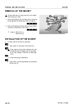


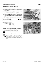


REMOVAL OF THE BLADE
1 - Rotate the turret 90ë and rest the working equipment
on the ground.
2 - Disconnect the cylinder from the blade. (For details,
see «REMOVAL OF THE BLADE CYLINDER»).
3 - Attach the blade to some hoisting tackle, using the la-
teral holes provided (1) and the cylinder attachment
(2).
H
Adjust the length of the cables to balance the
group.
4 - Take out the pin (3).
5 - Remove the blade (4).
Blade: PC12R: 43 kg
PC15R: 54 kg
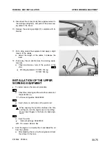
INSTALLATION OF THE BLADE
.
To install, reverse the removal procedure.
Internalbushings: ASL800050
When aligning the positions between the hole
and the pin, turn the engine over at low idling.
Do not insert fingers in the holes to check align-
ment.
30-82
REMOVAL AND INSTALLATION
BLADE
PC12R-8 PC15R-8
RKPA1650
1
2
1
4
RKPA1660
3
3
Summary of Contents for PC12R-8 MISTRAL
Page 1: ......
Page 2: ...40 28 PC15R 8 ...
Page 4: ...00 2 PC12R 8 PC15R 8 ...
Page 17: ...GROUP 10 ...
Page 18: ...40 28 PC15R 8 ...
Page 30: ...10 12 PC12R 8 PC15R 8 PAGE INTENTIONALLY LEFT BLANK ...
Page 32: ...10 14 PC12R 8 PC15R 8 PAGE INTENTIONALLY LEFT BLANK ...
Page 34: ...10 16 PC12R 8 PC15R 8 PAGE INTENTIONALLY LEFT BLANK ...
Page 36: ...10 18 PC12R 8 PC15R 8 PAGE INTENTIONALLY LEFT BLANK ...
Page 38: ...10 20 PC12R 8 PC15R 8 PAGE INTENTIONALLY LEFT BLANK ...
Page 40: ...10 22 PC12R 8 PC15R 8 PAGE INTENTIONALLY LEFT BLANK ...
Page 42: ...10 24 PC12R 8 PC15R 8 PAGE INTENTIONALLY LEFT BLANK ...
Page 44: ...10 26 PC12R 8 PC15R 8 PAGE INTENTIONALLY LEFT BLANK ...
Page 79: ...10 61 PC12R 8 PC15R 8 PAGE INTENTIONALLY LEFT BLANK ...
Page 130: ...10 112 PC12R 8 PC15R 8 PAGE INTENTIONALLY LEFT BLANK ...
Page 132: ......
Page 133: ...GROUP 20 ...
Page 134: ...40 28 PC15R 8 ...
Page 158: ...20 24 PC12R 8 PC15R 8 PAGE INTENTIONALLY LEFT BLANK ...
Page 198: ......
Page 199: ...GROUP 30 ...
Page 200: ...40 28 PC15R 8 ...
Page 283: ...GROUP 40 ...
Page 284: ...40 28 PC15R 8 ...
Page 317: ...40 33 PC12R 8 PC15R 8 PAGE INTENTIONALLY LEFT BLANK ...
Page 324: ......