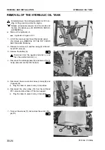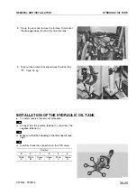
8 - Tip up the seat and remove the toolbox. Disconnect
the drainage tubes (13) and (14) from the tank.
9 - Take out the screws (15) and remove the tank (16).
Tank: 16 kg
INSTALLATION OF THE HYDRAULIC OIL TANK
.
To install, reverse the removal procedure.
H
Connect first the positive te).and then the
negative terminal(±)
H
Make sure that the threading of the filter head is leak-
tight.
H
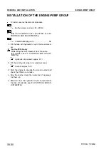
Carefully check the connection on the PPC valve.
Position
P
T
1
2
3
4
White
S
White
M
Green
R
Green
C
Blue
L
Green
A
30-25
REMOVAL AND INSTALLATION
HYDRAULIC OIL TANK
PC12R-8 PC15R-8
RKPA0840
13
14
RKPA0850
16
15
15
RKPB5980
1
2
3
4
P
T
Summary of Contents for PC12R-8 MISTRAL
Page 1: ......
Page 2: ...40 28 PC15R 8 ...
Page 4: ...00 2 PC12R 8 PC15R 8 ...
Page 17: ...GROUP 10 ...
Page 18: ...40 28 PC15R 8 ...
Page 30: ...10 12 PC12R 8 PC15R 8 PAGE INTENTIONALLY LEFT BLANK ...
Page 32: ...10 14 PC12R 8 PC15R 8 PAGE INTENTIONALLY LEFT BLANK ...
Page 34: ...10 16 PC12R 8 PC15R 8 PAGE INTENTIONALLY LEFT BLANK ...
Page 36: ...10 18 PC12R 8 PC15R 8 PAGE INTENTIONALLY LEFT BLANK ...
Page 38: ...10 20 PC12R 8 PC15R 8 PAGE INTENTIONALLY LEFT BLANK ...
Page 40: ...10 22 PC12R 8 PC15R 8 PAGE INTENTIONALLY LEFT BLANK ...
Page 42: ...10 24 PC12R 8 PC15R 8 PAGE INTENTIONALLY LEFT BLANK ...
Page 44: ...10 26 PC12R 8 PC15R 8 PAGE INTENTIONALLY LEFT BLANK ...
Page 79: ...10 61 PC12R 8 PC15R 8 PAGE INTENTIONALLY LEFT BLANK ...
Page 130: ...10 112 PC12R 8 PC15R 8 PAGE INTENTIONALLY LEFT BLANK ...
Page 132: ......
Page 133: ...GROUP 20 ...
Page 134: ...40 28 PC15R 8 ...
Page 158: ...20 24 PC12R 8 PC15R 8 PAGE INTENTIONALLY LEFT BLANK ...
Page 198: ......
Page 199: ...GROUP 30 ...
Page 200: ...40 28 PC15R 8 ...
Page 283: ...GROUP 40 ...
Page 284: ...40 28 PC15R 8 ...
Page 317: ...40 33 PC12R 8 PC15R 8 PAGE INTENTIONALLY LEFT BLANK ...
Page 324: ......

