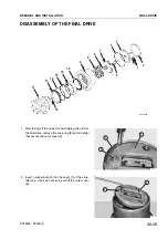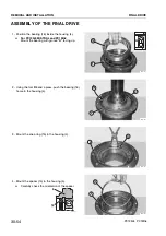
9 - Position the housing (4) with the bearing (16) suppor-
ted by the tool
D3
. Position the hydraulic motor (11)
and use a press to push it into the housing (4).
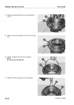
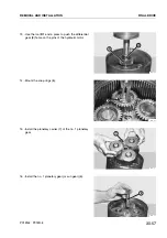
10 - Position the centering ring (12) on the hydraulic motor
(11) and, using a press and a push rod, press it home.
11 - Mount the snap-ring (15) in the seating of the hydrau-
lic motor (11).
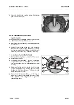
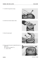
12 - Mount the no. 2 planetary gear on the pins of the hy-
draulic motor.
H
Keep a carefulcheck on the direction of assem-
bly.
30-56
REMOVAL AND INSTALLATION
FINAL DRIVE
PC12R-8 PC15R-8
RKPA1920
11
D
3
4
RKPA1930
12
RKPA1760
10
11
RKPA1940
9
RKP05430
9
Summary of Contents for PC12R-8 MISTRAL
Page 1: ......
Page 2: ...40 28 PC15R 8 ...
Page 4: ...00 2 PC12R 8 PC15R 8 ...
Page 17: ...GROUP 10 ...
Page 18: ...40 28 PC15R 8 ...
Page 30: ...10 12 PC12R 8 PC15R 8 PAGE INTENTIONALLY LEFT BLANK ...
Page 32: ...10 14 PC12R 8 PC15R 8 PAGE INTENTIONALLY LEFT BLANK ...
Page 34: ...10 16 PC12R 8 PC15R 8 PAGE INTENTIONALLY LEFT BLANK ...
Page 36: ...10 18 PC12R 8 PC15R 8 PAGE INTENTIONALLY LEFT BLANK ...
Page 38: ...10 20 PC12R 8 PC15R 8 PAGE INTENTIONALLY LEFT BLANK ...
Page 40: ...10 22 PC12R 8 PC15R 8 PAGE INTENTIONALLY LEFT BLANK ...
Page 42: ...10 24 PC12R 8 PC15R 8 PAGE INTENTIONALLY LEFT BLANK ...
Page 44: ...10 26 PC12R 8 PC15R 8 PAGE INTENTIONALLY LEFT BLANK ...
Page 79: ...10 61 PC12R 8 PC15R 8 PAGE INTENTIONALLY LEFT BLANK ...
Page 130: ...10 112 PC12R 8 PC15R 8 PAGE INTENTIONALLY LEFT BLANK ...
Page 132: ......
Page 133: ...GROUP 20 ...
Page 134: ...40 28 PC15R 8 ...
Page 158: ...20 24 PC12R 8 PC15R 8 PAGE INTENTIONALLY LEFT BLANK ...
Page 198: ......
Page 199: ...GROUP 30 ...
Page 200: ...40 28 PC15R 8 ...
Page 283: ...GROUP 40 ...
Page 284: ...40 28 PC15R 8 ...
Page 317: ...40 33 PC12R 8 PC15R 8 PAGE INTENTIONALLY LEFT BLANK ...
Page 324: ......

